

Recirculating Sand/Media Filters...
Description...
Recirculating filters using sand, gravel, or other media provide advanced secondary treatment of settled wastewater or
septic tank effluent. They consist of a lined (e.g., impervious PVC liner on sand bedding) excavation or structure filled with uniform washed sand that is placed over an underdrain system (see Figure 1). The wastewater is dosed onto the surface
of the sand through a distribution network and allowed to percolate through the sand to the underdrain system. The
underdrain system collects and recycles the filter effluent to the recirculation tank for further processing or discharge.
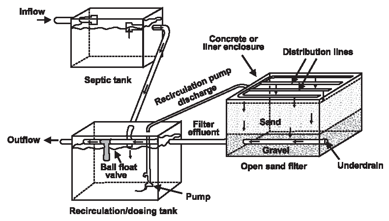
Figure 1. Typical recirculating sand filter system.
Recirculating sand filters (RSFs) are aerobic, fixed-film bioreactors. Other treatment mechanisms that occur in sand
filters include physical processes, such as straining and sedimentation, that remove suspended solids within the pores of
the media. Also, chemical sorption of pollutants onto media surfaces plays a finite role in the removal of some chemical (e.g., phosphorus) constituents. Bioslimes from the growth of microorganisms develop as films on the sand particle surfaces. The microorganisms in the slimes absorb soluble and colloidal waste materials in the wastewater as it percolates over the sand surfaces. The absorbed materials are incorporated into a new cell mass or degraded under aerobic conditions to carbon dioxide and water.
Most biochemical treatment occurs within approximately 6 inches of the filter surface. As the wastewater percolates
through this layer, suspended solids and carbonaceous biochemical oxygen demand (BOD) are removed. Most suspended solids
are strained out at the filter surface. The BOD is nearly completely removed if the wastewater retention time in the sand media is sufficiently long for the microorganisms to absorb waste constituents. With depleting carbonaceous BOD in the percolating wastewater, nitrifying microorganisms are able to thrive deeper in the surface layer, where nitrification will readily occur.
Chemical adsorption can occur throughout the media bed. Adsorption sites in the media are usually limited, however. The capacity of the media to retain ions depends on the target constituent, the pH, and the mineralogy of the media. Phosphorus is one element of concern that can be removed from wastewater in this manner, but the number of available adsorption sites
is limited by the characteristics of the media.
The basic components of recirculating filters include a recirculation/dosing tank, pump and controls, distribution network, filter bed with an underdrain system, and a return line. The return line or the underdrain must split the flow to recycle a portion of the filtrate to the recirculation/dosing tank. A small volume of wastewater and filtrate is dosed to the filter surface on a timed cycle 1 to 3 times per hour. Recirculation ratios are typically between 3:1 and 5:1. In the recirculation tank, the returned aerobic filtrate mixes with the anaerobic septic tank effluent before being reapplied to the filter.
Recirculating filters must use a coarser media than single-pass filters because recirculation requires higher hydraulic loadings. Both coarse sand and fine gravel are used as filter media. Because of the high hydraulic conductivities of the coarse media, filtrate recirculation is used to provide the wastewater residence times in the media necessary to meet the treatment requirements. Based on forward flow, daily hydraulic loadings are typically about 3 gpd/ft2 (2 to 5 gpd/ft2) when the filter media is coarse sand. Therefore, the corresponding combined daily filter hydraulic loading, including the recirculated flow, may be 6 to 25 gpd/ft2. Where gravel is used as the media, the daily hydraulic loadings are increased to as much as 10 to 15 gpd/ft2 with a combined daily loading of 30 to 75 gpd/ft2. BOD and TSS removals are generally the same as those achieved by single-pass filters. Nearly complete ammonia removal by nitrification is also achieved. In addition, the mixing of the return filtrate anaerobic septic tank effluent removes approximately 50 percent of the total nitrogen. However, because of the greater hydraulic loadings and coarser media, fecal coliform removal is somewhat less than in single-pass filters.
Recirculating filters offer advantages over single-pass filters. Greater control of performance is possible because recirculation ratios can be changed to optimize treatment. The filter can be smaller because of the higher hydraulic
loading. Recirculation also reduces odors because the influent wastewater (septic tank effluent) is diluted with return filtrate that is low in BOD and high in dissolved oxygen.
Many types of media are used in packed-bed filters. Washed, graded sand was the most common, but pea gravel has generally replaced it in recent times. Other granular media used include crushed glass, garnet, anthracite, plastic, expanded clay, expanded shale, open-cell foam, extruded polystyrene, and bottom ash from coal-fired power plants. Coarse-fiber synthetic textile materials are also used. These materials are generally restricted to proprietary units. Contact the system manufacturers for application and design using these materials.
Other modifications to the basic RSF design include the type of distribution system, the location and design of the recirculation tank, the means of flow splitting the filtrate between discharge and return flows, and enhancements to improve nitrogen removal.
Applications...
Recirculating sand filters can be used for a broad range of applications, including single-family residences, large commercial establishments, and small communities. They are frequently used to pretreat wastewater prior to subsurface infiltration on sites where soil has insufficient unsaturated depth above ground water or bedrock to achieve adequate treatment. They are also used to meet water quality requirements before direct discharge to a surface water. RSFs are primarily used to treat domestic wastewater, but they have also been used successfully in treatment trains to treat wastewaters high in organic materials such as those from restaurants and supermarkets. Single-pass filters are most frequently used for smaller applications and at sites where nitrogen removal is not required. Recirculating filters are
used for both large and small flows and are frequently used where nitrogen removal is necessary. RSFs frequently replace aerobic package plants in many parts of the country because of their high reliability and lower O/M requirements.
Design...
Packed-bed filter design starts with the selected media. The media characteristics determine the necessary filter area,
dose volumes, and dosing frequency. Availability of media for a specific application should be determined before completing the detailed design. The sand or gravel selected should be durable with rounded grains. Only washed material should be used. Fine particles passing the U.S. No. 200 sieve (<0.074 mm) should be limited to less than 3 percent by weight. Other granular media are bottom ash, expanded clay, expanded shale, and crushed glass. These media should perform similarly to sand and gravel for similar effective sizes, uniformity, and grain shape. Newer commercial media such as textile materials have had limited testing, but should be expected to perform as well as the above types.
Traditionally, media filters have been designed based on hydraulic loadings. However, since they are primarily aerobic biological treatment units, it is more appropriate that they be designed based on organic loadings. Unfortunately, insufficient data exist to establish well-defined organic loading rates. Experience suggests that BOD5 loadings
on sand media should not exceed about 5 lb/1,000 ft2 per day (0.024 kg/m2 per day) where the effective size is approximately 1.0 mm and the dosing rate is at least 12 times per day. Higher loadings have been measured in short-term studies, but designers are cautioned about exceeding this loading rate until quality-assured data confirm these higher levels. The BOD5 loading should decrease with decreasing effective size of the sand. Because of the larger pore size and greater permeability, gravel filters can be loaded more heavily. BOD5 loadings of 20 lb/1,000 ft2 per day (0.10 kg/m2 per day) have been consistently successful, but again higher loadings have
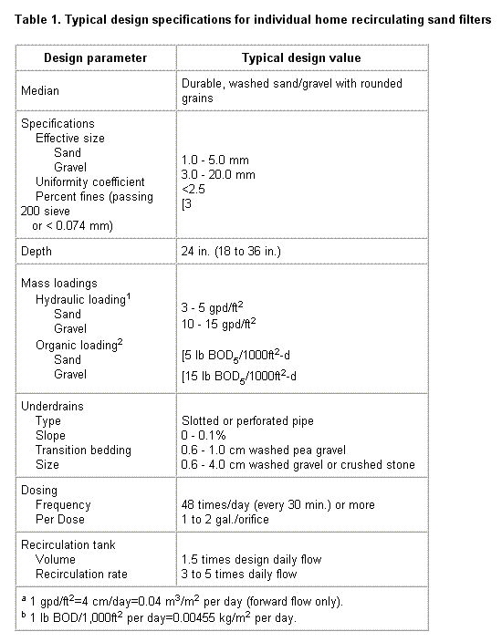
been measured. Some often-quoted design specifications for RSFs are given in Table 1.
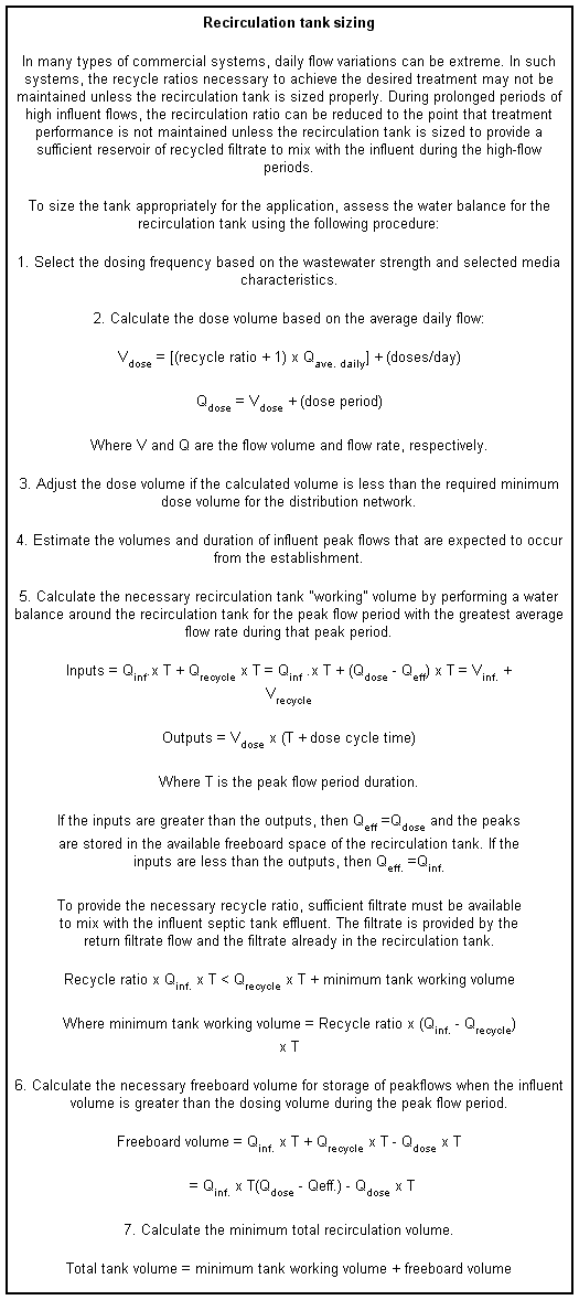
The RSF dose volume depends on the recirculation ratio, dosing frequency, and distribution network :
Dose Volume = Design Flow (gpd) x (Recirculation Ratio + 1) ÷ Number of Doses/Day
Small dose volumes are preferred because the flow through the porous media will occur under unsaturated conditions with higher moisture tensions. Better wastewater media contact and longer residence times occur under these conditions. Smaller dose volumes are achieved by increasing the number of doses per day.
The recirculation ratio increases the hydraulic loading without increasing the organic loading. For example, a 4:1 recirculation ratio results in a hydraulic loading of five times the design flow (1 part forward flow to 4 parts recycled flow). The increased hydraulic loading reduces the residence time in the filter so that recirculation is necessary to
achieve the desired treatment. Typical recirculation ratios range from 3:1 to 5:1. As the permeability of the media increases, the recirculation ratio may need to increase to achieve the same level of treatment.
Media characteristics can limit the number of doses possible. Media reaeration must occur between doses. As the effective size of the media decreases, the time for drainage and reaeration of the media increases. For single pass filters, typical dosing frequencies are once per hour (24 times/day) or less. Recirculating sand filters dose 2 to 3 times per hour (48 to
72 times/day).
Distribution network requirements will also limit the number of doses possible. To achieve uniform distribution over the filter surface, minimum dose volumes are necessary and can vary with the distribution method selected. Therefore, if the
dose volume dictated by the distribution network design is too high, the network should be redesigned. Since the dose
volume is a critical operating parameter, the method of distribution and the distribution system design should be considered carefully.
Distribution methods used include rigid pipe pressure networks with orifices or spray nozzles, and drip emitters. Rigid
pipe pressure networks are the most commonly used method. Orifices with orifice shields, facing upward, minimize hole blockage by stones. Since the minimum dose volume required to achieve uniform distribution is five times the pipe volume, large multihome filters are usually divided into multiple cells. Drip emitter distribution is being used increasingly because the minimum dose volumes are much less than the rigid pipe network volumes.
Recirculation tanks are a component of most recirculation filter systems. These tanks consist of a tank, recirculation pump and controls, and a return filter water flow splitting device. The flow splitting device may or may not be an integral part of the recirculation tank. Recirculation tanks store return filtrate, mix the filtrate with the septic tank effluent, and store peak influent flows. The tanks are designed to either remain full or be pumped down during periods of low wastewater flows. Since doses to the recirculating filter are of a constant volume and occur at timed intervals, the water level in the tank will rise and fall in response to septic tank effluent flow, return filtrate flow, and filter dosing.
In tanks designed to remain full, all filtrate is returned to the recirculation tank to refill the tank after each dosing event. When the tank reaches its normal full level, the remaining return filtrate is discharged out of the system as effluent. This design is best suited where treatment performance must be maintained continuously. For single-family home systems, the recirculation tank is typically sized to be equal to 1.5 times the design peak daily flow.
When the filtrate flow is continuously split between the return (to the recirculation tank) and the discharge, the liquid volume in the recirculation tank will vary depending on wastewater flows. During low flow periods the tank can be pumped
down to the point that the low-water pump off switch is activated. This method leaves less return filtrate available to
mix with the influent flow. While simple, this method of flow splitting can impair treatment performance because minimum recirculation ratios cannot be maintained. This is less of a disadvantage, however, for large, more continuous flows
typical in small communities or large cluster systems.
The recirculation pump and controls are designed to dose a constant volume of mixed filtrate and septic tank effluent flow onto the filter on a timed cycle. The pump must be sized to provide the necessary dosing rate at the operating discharge
head required by the distribution system. Pump operation is controlled by timers that can be set for pump time on and pump time off. A redundant pump-off float switch is installed in the recirculation tank below the minimum dose volume level. A high water alarm is also installed to provide notice of high water caused by pump failure, loss of pump calibration, or excessive influent flows.
Several flow splitting devices may be used. The most common are ball float valves and proportional splitters. The ball
float valve is used where the recirculation tank is designed to remain full. The valve is connected to the return filtrate line inside the recirculation tank (see Figure 2). The return line runs through the tank. The ball float valve is open
when the water level is below the normally full level. When the tank fills from either the return filtrate or the influent flow, the ball float rises to close the valve, and the remaining filtrate is discharged from the system. The proportional splitters continuously divide the flow between return filtrate and the filtrate effluent (see Figure 3). Another type of splitter consists of a sump in which two pipes are stubbed into the bottom with their ends capped. In the crowns of each capped line, a series of equal-sized, pluggable holes are drilled. The return filtrate floods the sump, and the flow is
split in proportion to the relative number of holes left open in each perforated capped pipe.
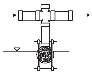
Figure 2. Flow splitter operated by a floatball valve.
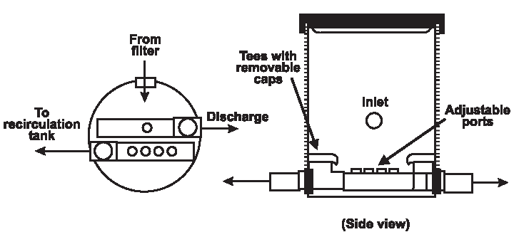
Figure 3. Splitter basin.
Another type of splitter divides flow inside the filter. The filter floor is raised so that it slopes in opposite
directions. The raised point is located so that the ratio of the floor areas on either side is in proportion to the
desired recirculation ratio. Each side has its own underdrain. One side drains back to the recirculation tank, the other
side drains to discharge. This method has the disadvantage that adjustments to the recirculation ratio cannot easily be
made.
Most RSFs are constructed aboveground and with an open filter surface; however, in cold climates, they can be placed in
the ground to prevent freezing. Placing a cover over an RSF is recommended to reduce odors and to provide insulation in
cold climates, although no freezing was observed in an open RSF in Canada using coarse gravel media. Covers must provide ample fresh air venting, because reaeration of the filter media occurs primarily from the filter surface.
The filter basin can be a lined excavation or fabricated tank. For single-home systems, prefabricated concrete tanks are commonly used. Many single-home filters and most large filters are constructed within lined excavations. Typical liner materials are polyvinyl chloride and polypropylene. A liner thickness of 30 mil can withstand reasonable construction activities yet be relatively easy to work with. A sand layer should be placed below the liner to protect it from puncturing if the floor and walls of the excavation are stony. The excavation walls should be brought above the final grade to prevent entry of surface water. It is often necessary to cover the filter surface to reduce the effects of algae fouling, odors,
cold weather impacts, precipitation, and snow melt. The cover must provide ample fresh air venting, however. Reaeration of the filter media primarily occurs from the filter surface.
The underdrain system is placed on the floor of the tank or lined excavation (Figure 4). Ends of the underdrains should be brought to the surface of the filter and fitted with cleanouts that can be used to clean the underdrains of biofilms if necessary. The underdrain outlet is cut in the basin wall such that the drain invert is at the floor elevation and the
filter can be completely drained. The underdrain outlet invert elevation must be sufficiently above the recirculation tank inlet to accommodate a minimum of 0.1 percent slope on the return line and any elevation losses through the flow splitting device. The underdrain is covered with washed, durable gravel to provide a porous medium through which the filtrate can flow to the underdrain system. The gravel should be sized to prevent the filter media from mixing into the gravel, or a layer of 1/4- to 3/8-inch-diameter gravel should be placed over the underdrain gravel before the filter media is added.
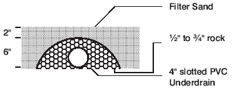
Figure 4. Typical underdrain detail.
Performance...
RSF systems are extremely effective and reliable in removing BOD, TSS, and contaminants that associate with the
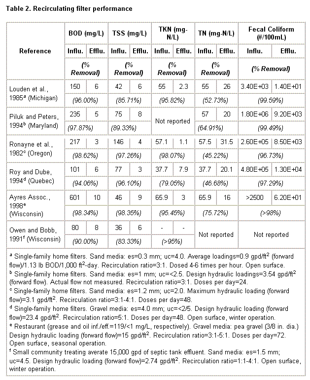
particulate fraction of the incoming septic tank effluent. Some typical performance data are provided in Table 2.
Normally, BOD and TSS effluent concentrations are less than 10 mg/L when RSF systems are treating residential wastewater. Nitrification tends to be complete, except in severely cold conditions. Natural denitrification in the recirculating tank results in 40 to 60 percent removal of total nitrogen (TN). Fecal coliform removal is normally 2 to 3 logs (99 to 99.9 percent). Phosphorus removal drops off from high percentages to about 20 to 30 percent after the exchange capacity of the media becomes exhausted. Some media and media mixes have very high iron and/or aluminum content that extends the initial period of high phosphorus removal.
Management Needs...
As with all treatment systems, the RSF should be constructed carefully according to design specifications using corrosion-resistant materials. Every truckload of media delivered to the site should be tested for compliance with the specifications. All tanks and lined basins, including the entry and exit plumbing locations, must be watertight.
Inspection and operation/maintenance (O/M) needs are primarily related to inspection and calibration of the recirculation pump and controls. For sand media units, frequent removal of vegetation and scraping of the surface are required. Regular maintenance tasks include periodic checks on the pressure head at the end of the distribution system, draining of the accumulated solids from lines, and occasional brushing of the lines (at least once per year), with bottle brushes attached
to a plumber's snake.
The recirculation tank should be checked for sludge accumulation on each visit and pumped as necessary (usually one to
three times per year).
Risk Management Issues...
RSFs are extremely reliable treatment devices and are quite resistant to flow variations. Toxic shocks are detrimental
to RSF treatment performance because of the resistance of biofilms to upset and the extended period of contact between biofilms and wastewater.
Gravel RSFs (or RGFs) are likely viable throughout the United States when proper precautions (e.g., covering, insulation)
are taken. These systems perform best in warmer climates, but they increase opportunities for odor problems. In general, gravel RSF systems are far less prone to odor production than ISFs. Increased recycle ratios should help minimize such problems. However, power outages will stop the process from treating the wastewater, and prolonged outages would be likely
to generate some odors.
Costs...
Construction costs for recirculating sand filters are driven by treatment media costs, the recirculating tank and pump/ control system costs, and containment costs. Total costs are therefore site specific, but tend to vary from $8,000 to $11,000. Low-cost alternative media can reduce this figure significantly. Power costs for pumping at 3 to 4 kWh/day are in the range of $90 to $120 per year, and management costs for monthly visits/inspections by semiskilled personnel typically cost $150 to $200 annually.


