


| Country... | Number... | Block... |
| Bahrain | 12 | 40 |
| Norway | 72 | 10 / 15 |
| Belgium | 160 | 10 / 15 |
| Pakistan | 40 | 15 |
| Brazil | ? | 15 |
| Portugal | 20 | 15 |
| Denmark | 58 | 10 / 15 |
| Singapore | 46 | 15 |
| Egypt | 80 | 15 / 32 / 40 |
| South Korea | 36 | 32 / 52 |
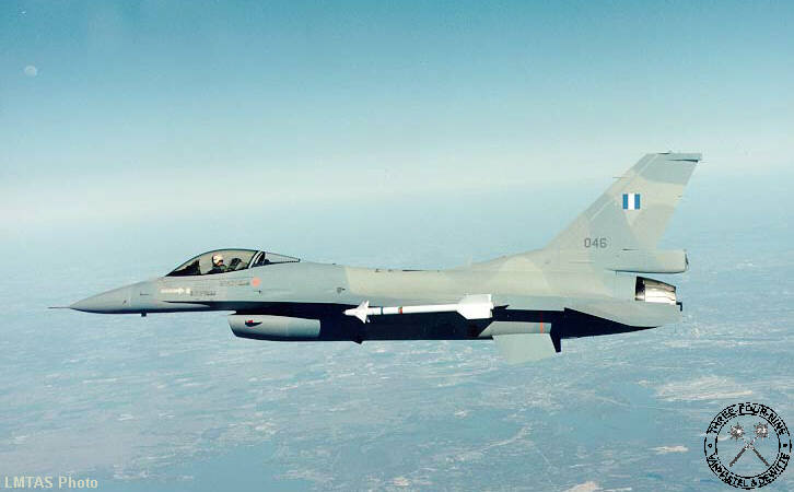
| Greece | 80 | 30 |
| Republic of China | ? | 120 / 30 |
| Indonesia | 12 | 15 |
| Thailand | 34 | 15 |
| Israel | 150 | ? |
| Turkey | 152 | 30 / 40 / 50 |
| Japan | ? | ? |
| United Arab Emirates | 80 | ? |
| Jordan | 16 | ? |
| USA | 1,985 | 10 / 15 / 20 / 25 / 30 / 32 / 40 / 42 |
| Netherlands | 213 | 10 / 15 |
| New Zealand | 30 | ? |
| Venezuela | 24 | 15 |