Aeration - 2...

Introduction...

In aerobic metabolism oxygen acts primarily as an electron acceptor for catabolism. As the activated sludge process is designed to be substrate - limiting, metabolism sets the rate of oxygen demand. The function of the aeration system is to transfer oxygen to the liquid at such a rate that oxygen never becomes the limiting factor in process operation ( i.e., never limits the rate of organic utilization or other metabolic functions ). It is the engineer's responsibility to ensure that aeration systems are adequate. This requires an understanding of the basic principles of gas transfer as well as some familiarity with the different types of aeration devices that are available.

Fundamentals of Gas Transfer...

All solutes tend to diffuse through solutions until the composition is homogeneous throughout. The rate at which solutes diffuse across a uniform cross - sectional area depends on the molecular size and shape and the concentration gradient of that substance. Matter moves spontaneously from a region of high concentration toward a region of lower concentration, and the more the concentration is decreasing, the more the diffusion rate increases. This can be expressed by writing the concentration gradient term as ( - aC / aY ), where C is the concentration and Y the distance. If ( aM / at ) represents the rate at which M grams of solute cross the reference plane, " Fick "s first law of diffusion states that ;

( aM / at ) = - ( D L ) ( A ) ( aC / aY )

where ; aM / at : rate of mass transfer ( mass time - 1 ), D L : diffusivity constant ( area time - 1 ), A : cross - sectional area across which the solute is diffusing ( area ) and aC / aY : concentration gradient ( i.e., the change in concentration with distance, mass volume - 1 length - 1 ).

The simplest concept of a gas transfer process is the " stationary liquid film theory ". This theory suggest that at the interface between the gas phase and the liquid phase, there exists a stationary liquid film in which gas molecules are concentrated. The gas concentration is not homogeneous throughout the liquid film but rather decreases from the saturation concentration given by " Henry "s law to some lower concentration at the film / bulk liquid boundary. Figure given below illustrates the stationary liquid film theory.


In this figure, C S represents the saturation concentration of the gas in the liquid as predicted by " Henry "s law, C the concentration of the gas in the bulk of the liquid, Y F the thickness of the film, and C L the gas concentration at the film / bulk liquid boundary. Applying " Fick "s first law of diffusion to this situation gives ;

( aM / at ) = - ( D L ) ( A ) ( aC / aY F )

In this case, A represents the interfacial area of contact between the gas and liquid phases. Since the liquid film thickness is small ( only a few molecules thick ), it is possible to approximate the differential quantity ( aC / aY F ) with linear approximation ;

( aC / aY F ) ==== ( C S - C ) / ( Y F )

The system, as described by the linear approximation, is shown in figure given below. For the linear approximation, equation reduces from a partial differential equation in time and space to an ordinary differential equation in time.

( dM / dt ) = - ( D L ) ( A ) [ ( C S - C ) / ( Y F ) ]


Dividing both sides of the equation by V ( the volume of the liquid phase ), the equation becomes ;

[ ( 1 / V ) ( dM / dt ) ] = - ( D L ) ( A / V ) [ ( C S - C ) / ( Y F ) ]

Since the term [ ( 1 / V ) ( dM / dt ) ] has the units of mass volume - 1 time - 1 or concentration per unit time, this term can be expressed by the differential equation ( dC / dt ) ;

[ ( 1 / V ) ( dM / dt ) ] = ( dC / dt )

( dC / dt ) = - ( D L ) ( A / V ) [ ( C S - C ) / ( Y F ) ]

Because the value of the film thickness is normally unknowm, it is usually combined with D L to define a new constant term.

K L = ( D L ) / ( Y F )

where ; K L represents the gas transfer coefficient and has the units of length time - 1 . K L can be incorporated into the equation to give an expression which has the form ;

( dC / dt ) = - ( K L ) ( A / V ) ( C S - C )

This equation represents the change in concentration to be expected as molecules diffuse from a region of high concentration to a region of low concentration so that the concentration is decreasing with time. When the gas concentration increases with time during the aeration process, the negative sign is dropped and equation reduces to ;

( dC / dt ) = ( K L ) ( A / V ) ( C S - C )

In most cases the interfacial area of contact, A, is difficult to determine. To circumvent this problem, a second constant, K L a, is introduced. This constant has a value equal to the product of K L and ( A / V ) ;

K L a = ( K L ) ( A / V )

K L a is defined as the overall gas transfer coefficient and has the units of time - 1 .

( dC / dt ) = ( K L a ) ( C S - C )

[ ( dC ) / ( C S - C ) ] = ( K L a ) ( dt )

- ln ( C S - C ) ==== ( K L a ) ( t ) + Constant of integration

If C = C 0 at t = 0, the constant of integration has the value - ln ( C S - C 0 ) ;

- ln ( C S - C ) = ( K L a ) ( t ) - ln ( C S - C 0 )

ln [ ( C S - C 0 ) / ( C S - C ) ] = ( K L a ) ( t )

This implies that a semilog plot of [ ( C S - C 0 ) / ( C S - C ) ] versus t will give a linear trace with a slope equal to ( K L a / 2.3 ) in log base. Some typical C S values for pure water are given in table shown below.

Temperature ( O C ) C S ( mg / L )
0 14.62
2 13.84
4 13.13
6 12.48
8 11.87
10 11.33
12 10.83
14 10.37
16 9.95
18 9.54
20 9.17
22 8.83
24 8.53
26 8.22
28 7.92
30 7.63
Atmosphere contains 21 % oxygen, chloride concentration = 0.00 mg / L and pressure = 1 atm.

Factors Affecting Oxygen Transfer...

Such factors are ; ( 1 ) oxygen saturation, ( 2 ) temperature, ( 3 ) wastewater characteristics and ( 4 ) degree of turbulance.

Oxygen Saturation...

The saturation concentration of oxygen in water depends upon salinity, temperature, and the partial pressure of the oxygen in contact with the water. " Eckenfelder " and " O'Connor " suggest that the saturation concentration may be obtained from the following equation ;

C S - 760 = [ 475 - ( 2.65 ) ( S ) ] / ( 33.5 + T )

where ; C S - 760 : saturation value of oxygen at a total atmospheric pressure of 760 mm Hg ( mg / L ), S : dissolved solids concentration in the water ( g / L ) and T = temperature ( O C ).

Many workers correct for the presence of dissolved salts by introducing a BETA factor, defined as ;

BETA = ( Saturation concentration in wastewater ) / ( Saturation concentration in tap water )

The value of oxygen saturation given by the equation may be corrected for prevailing pressure by applying the expression ;

C S = ( C S - 760 ) [ ( P - p ) / ( 760 - p ) ]

where ; P : prevailing barometric pressure ( mm Hg ) and p : saturated water vapor pressure at the temperature of the water ( See the table given below ).

Temperature ( O C ) Vapor pressure ( mm Hg )
0 4.5
5 6.5
10 9.2
15 12.8
20 17.5
25 23.8
30 31.8

Temperature...

Temperature affects the overall oxygen transfer coefficient according to the following expression ;

K L a T = ( K L a 20 C ) ( 1.020 ) T - 20

" Dobbins " have proposed another approach wherein K L a is corrected for both temperature and viscosity effects ;

[ ( K L a 1 ) / ( K L a 2 ) ] = { [ ( T 1 ) ( MU 2 ) ] / [ ( T 2 ) ( MU 1 ) ] }

where ; T : temperature ( O K ) and MU : absolute viscosity.

Wastewater Characteristics...

Surface - active agents such as short - chain fatty acids and alcohols are soluble in both water and oil solvents. The hydrocarbon part of the molecule is responsible for its solubility in oil, while the polar carboxyl or hydroxyl group has sufficient affinity to water to drag a short - length nonpolar hydrocarbon chain into aqueous solution. These molecules will concentrate at an air / water interface, where they are able to locate their hydrophilic group in the aqueous phase, which allows the hydrophobic hydrocarbon chain to extend into the vapor phase ( see figure given below ). This situation is energetically more favorable but creates a concentration of molecules or " film " that retards molecular diffusion. Hence, resistance to oxygen transfer is increased and, consequently the value of K L a is decreased. To compensate for the effects of surface - active agents on oxygen transfer, an ALPHA factor is introduced, where ;

ALPHA = ( K L a of wastewater ) / ( K L a of tap water )

Turbulence...

" Eckenfelder " and " Ford " report that the degree of turbulence in the aeration tank will influence the value of ALPHA as follows ;

( 1 ) Under near - quiescent conditions ( a lower degree of turbulence ), fluid motion has little effect on ALPHA because the resistance to diffusion in the bulk of the liquid is greater than the film resistance.

( 2 ) Increasing fluid agitation to a moderate degree decreases the resistance to diffusion in the liquid bulk so that film resistance will control the diffusion rate. At this point ALPHA is depressed to a minimum value.

( 3 ) A further increase in fluid agitation will produce a high degree of turbulence and break up the film. Under such conditions ALPHA will approach unity.

The effects of turbulence on ALPHA, as developed by " Mancy " and " Okun " are illustrated by figure given below.

Oxygen Transfer Rates...

The oxygen transfer rate of a particular aeration device quoted by a manufacturer applies only for standard conditions and a specific tank geometry. Standard conditions mean that the aerator was tested with tap water at zero dissolved oxygen concentration, 20 O C and 760 mm Hg atmospheric pressure. Thus, a manufacturer's figure for the rate of oxygen transfer must be modified for process conditions. This can be done by incorporating the factors that affect the oxygen transfer rate into the equation to give ;

( dC / dt ) ACTUAL = ( ALPHA ) ( K L a 20 C ) { [ ( P - p ) / ( 760 - p ) ] ( BETA ) ( C S ) - C }

Under standard conditions where C = 0 ;

( dC / dt ) STANDARD = ( K L a 20 C ) ( C S )

To determine the design oxygen transfer rate, equations given above must be combined as ;

( dC / dt ) ACTUAL / ( dC / dt ) STANDARD

Determination of K L a and ALPHA Values...

Either the steady - state or non - steady - state test is used to determine aeration equipment characteristics under process conditions. The basic formulation used in the steady - state test is developed by modifying the equation such that ;

( dC / dt ) OVERALL = ( K L a ) ( C S - C ) - R

where ; R : the oxygen utilization rate of the biomass and has the units mass volume - 1 time - 1 . The C S term reflected in the equation is specific for process conditions. At steady - state conditions the rate of oxygen transfer by the aeration system is equal to the rate of oxygen utilization by the biomass, implying that ( dC / dt ) OVERALL is equal to zero. Thus, equation given above can be solved for K L a to give ;

K L a = ( R ) / ( C S - C )

where ; K L a : overall oxygen transfer rate in wastewater at process conditions, time - 1 . This K L a value indicates the effects of surface active material, TDS, temperature, and partial pressure.

In the non - steady - state test, final effluent or supernatant from sttled mixed liquor is generally used. The laboratory procedure for this test is as follows ;

( 1 ) Adjust the liquid temperature to that expected in the field.

( 2 ) Deoxygenate the liquid in the test basin using sodium sulfite with a cobalt chloride catalyst. The cobalt chloride dose should be no greater than 0.05 mg / L. The reaction between sodium sulfite and oxygen is as follows ;


Theoretically, 7.9 mg / L of sodium sulfite is required for each mg / L of oxygen present. However, it is common practice to add 1.5 to 2.0 times this amount to ensure complete deoxygenation.

( 3 ) Oxygenate the liquid using the same type of aeration device to be used under process conditions.

( 4 ) Tabulate the dissolved oxygen concentration at various time intervals and sampling points until oxygen saturation is reached. Recommended sampling points for steady - state test is given in figure shown below ;


( 5 ) A plot of log [ ( C S - C 0 ) / ( C S - C ) ] versus time will give a linear trace of slope ( K L a ) / ( 2.3 ) ( See figure given below ).


( 6 ) Repeat the same procedure using tap water as the test liquid.

Some typical values of ALPHA and BETA are given in tables shown below.


Design of Aeration Systems...

The costliest item in the activated sludge process is the aeration system. Because of this, its design is critical if the treatment facility is to be cost - effective. Manufacturers of aeration devices will usually quote a figure for the oxygen transfer rate in terms of the mass of oxygen that the aerator can introduce into water per unit of time per unit of power input. This figure quoted by the manufacturer will be valid only under standard conditions and the specified tank geometry. It will, therefore, be necessary to adjust the manufacturer's figures to those which more realistically describe actual process conditions. Current methods used to transfer oxygen in aerobic biological wastewater treatment process include ;


( 1 ) Compressed air diffusion...


( 2 ) Submerged turbine aeration...


( 3 ) Low - speed surface aeration...


( 4 ) Motor - speed ( high ) surface aeration...


As a guide to system selection, diffused aeration not be used when the oxygen utilization rate exceeds 40 mg / L . h. Low speed surface aerators are acceptable as long as the oxygen utilization rate is less than 80 mg / L . h. However, when the oxygen utilization rate exceeds 80 mg / L . h, submerged turbine aeration should be the method of choice. Furthermore, in areas where freezing temperatures are experienced for long periods winter months, either diffused or submerged turbine aeration is preferred over surface aeration.

Diffused Aeration...

Fiffused air systems operate by blowing compressed air through diffusers. Compressed air is provided by compressors ( " blowers " ) operating at a pressure sufficient to overcome the head created by frictional losses in the air piping system and the static head of liquid above the diffuser.


Centrifugal " blower "...

The diffusers are positioned near the bottom and along the side wall of the aeration tank to effect oxygen transfer and mixing, or are evenly spaced across the bottom of the aeration tank. They may be attached to either fixed or retractable mountings. Such systems will generally provide adequate mixing with air flows of 20 to 30 standard cubic feet per minute ( scfm ) per 1,000 cubic feet of tank volume. Other commonly used figures for air flow in these systems are 1 cubic feet per gal wastewater treated or 1,000 cubic feet per lb BOD applied to the aeration tank. There are basically two types of diffusers. One type produces small bubbles by passing compressed air through a porous medium prior to its discharge into the liquid. The porous medium used is either a material composed of silicon dioxide or aluminum oxide grains held by a ceramic binder or plastic - wrapped ( e.g., " Saran " wrapped ) or plastic - cloth tubes. Diffusers of this type are termed " fine - bubble " diffusers and produce bubbles ranging in size from 2.0 to 2.5 mm. Even though the rate of oxygen transfer is greater with a smaller bubble size ( increased interfacial area of contact ), a large headloss is experienced through a fine - bubble diffuser, which increases the power requirement for these devices. They also clog fairly, and this increases the headloss even more.


Fine - bubble diffusers ( Click on to enlarge )...

The second type of diffuser, termed a " coarse - bubble " diffuser, produces bubbles up to 25 mm in size. Such diffusers may be of the nozzle, orifice, valve, or hydraulic shear type. Since the interfacial area of contact is less with a larger bubble size, the rate of oxygen transfer for this type of diffuser is less than that for fine - bubble diffusers. However, the coarse - bubble diffuser has the advantage of requiring less maintenance and less power. Examples of coarse - bubble diffusion units are ; ( a ) sparjet and ( b ) INKA.


Some diffuser types...

The relationship among oxygen transfer, air flow, and diffuser spacing is illustrated in figure given below for " Saran " wrapped diffusion units in a 15 ft deep by 24 ft wide aeration tank.


If adequate mixing is to be maintained, the width / depth ratio should not exceed 2. Tank width also affects oxygen transfer. This is illustrated in figure given below, which shows the effect of air flow on oxygen transfer for 8 - and 24 - ft wide aeration tanks using both " Saran " tube and sparjet aeration devices.


" Shell " and " Cassady " suggest that a diffuser depth between 8 and 16 ft usually gives the optimum balance between mixing and oxygen transfer rate. The relationship between oxygen transfer rate and diffuser depth is given in figure shown below for both " Saran " tube and sparjet aeration devices.


When coarse - bubble diffusers are used, an increase in air flow rate creates additional turbulence, which may shear the larger bubbles into smaller ones, thereby increasing the interfacial area of contact and resulting in an increase in the rate of oxygen transfer. Such an effect is illustrated in figures given below and 5 - 20 for a sparjet and INKA aeration systems, respectively.


There is a definite relationship between the rate of oxygen consumption, air floe rate, and percentage oxygen absorbed. " Morgan " and " Bewtra " presented the data in figure given below and noted that the rapid oxygen - consuming sulfite reaction removed only 22 % of the oxygen from air passing through water when the air flow rate was low, and this value dropped to 18 % when the flow rate was increased. When an oxygen - consuming reaction is not present, the system is even more sensitive to air flow rate. Figure given below suggests that as long as the oxygen demand is satisfied, the rate of air flow should be great enough to provide the required degree of mixing but no greater.


Diffused aeration systems use oxygen under air pressure and studies have shown that the oxygen saturation concentration which should be used to evaluate these systems is very nearly the one - third depth value. To determine the oxygen saturation concentration for such a system, " Stukenberg " recommended the use of the following equation ;

C SA = ( C S ) [ ( Pb / 59.84 ) + ( O T / 42 ) ]

where ; C SA : oxygen saturation concentration at the one - third depth ( mg / L ), C S : oxygen saturation concentration at the liquid surface ( mg / L ), Pb : air pressure at the point of release from diffuser ( in Hg ) and O T : percentage of oxygen in the air leaving the liquid surface ( % ), usually it is assumed that between 6 and 10 % of the oxygen is absorbed and that air initially contains 21 % oxygen.

Values for C S and Pb can be determined from the relationships given below ;

C S = [ ( P - p ) / ( 760 - p ) ] [ ( 475 - 2.65 S ) / ( 33.5 + T S ) ]

Pb = [ ( H / 2.3 ) + ( P / 760 ) ( 14.7 ) ] ( 2.036 )

where ; P : prevailing barometric pressure ( mm Hg ), p : saturated water vapor pressure at standard conditions ( mm Hg ), S : dissolved solids in the wastewater ( g / L ), T S : wastewater temperature at standard conditions ( i.e., at 20 O C ) and H : liquid depth at the point of bubble release ( ft ). The constant 2.036 is the conversion from pounds per square inch to inches of Hg.

Once a value of C SA has been determined, the oxygen transfer rate under process conditions is computed from the following equation ;

( T.R. ) ACTUAL = ( T.R. ) STANDARD ( ALPHA ) [ ( C SA - C ) / ( 9.2 ) ]

In this equation oxygen transfer rate, ( T.R. ), is expressed as pounds of oxygen transferred per hour per diffuser unit. C represents the desired minimum dissolved oxygen concentration to be maintained in the aeration tank and is usually taken as 2.0 mg / L. The value of 9.2 in the denominator is the oxygen saturation concentration at standard conditions.

The theoretical horsepower requirement for a diffused aeration system can be computed from a formula that describes adiabatic compression ;

Thp = ( 0.00436 ) ( Q 1 ) ( P 1 ) [ k / ( k - 1 ) ] [ ( P 2 / P 1 ) ( k - 1 ) / k ]

where ; Thp : theoretical blower horsepower requirement, k : ratio of specific heats at constant pressure to constant volume ( for adiabatic compression of diatomic molecules, k has a value near 1.395 ), P 1 : absolute inlet pressure ( psia ), P 2 : absolute outlet pressure ( psia ) ; this term can be estimated from the following expression when frictional losses are neglected ;

P 2 = [ ( GAMMA W ) ( H ) / ( 144 ) ] + ( P 1 )

GAMMA W : specific weight of water ( lb / cft ), H : liquid depth to point of bubble release ( ft ) and Q 1 : air flow at the intake ( cfm ).

Temperature
( O C )
GAMMA W
( lb / ft 3 )
0.0 62.42
4.4 62.43
10.0 62.41
15.5 62.37
21.1 62.30
26.6 62.22
32.2 62.11

Other useful expressions are ;

( P 2 / P 1 ) = ( T 2 / T 1 ) k / ( k - 1 )

where ; T 1 : air temperature at the intake ( O R, i.e., 460 + O F ) and T 2 : air temperature at the discharge point ( O R ).

Q 2 = [ ( n ) ( R ) ( T 2 ) ] / ( P 2 )

Q 2 : rate of air flow at the discharge point ( cfm ), R : gas constant ( = 10.73 ) and n : moles of oxygen transferred ( lb moles / min ), this term can be estimated from the following expression where the value for oxygen absorbed is the same as that used to compute O T ;

n = ( Oxygen required, lb / day ) / [ ( 32 lb / lb - mole ) ( 1,440 min / day ) ( 0.21 ) ( Fraction O 2 absorbed ) ]

and ;

Q 1 = [ ( P 2 ) ( Q 2 ) ( T 1 ) ] / [ ( P 1 ) ( T 2 ) ]

Air flows ( in cfm ) delivered by a diffuser system can be converted to standard cfm by applying the following formula ;

Q S = ( P 2 / P 0 ) ( T 0 / T 2 ) ( Q 2 )

where ; Q S : air flow at the discharge point ( scfm ), P 0 : standard pressure ( = 14.7 psi ) and T 0 : standard temperature ( = 32 O F = 492 O R ).

The brake horsepower ( required horsepower input to blower ) can be obtained from the expression ;

Bhp = ( Thp ) / ( e )

where ; e : blower efficiency ( % ), for centrifugal blowers and air flows greater than 15,000 cfm, values between 0.70 and 0.80 are used ; for rotary positive displacement blowers and air flows less than 15,000 cfm, values between 0.67 and 0.74 are generally applied.

When used in a biological process, the oxygen transfer rate of a diffused aeration system is usually between 1.50 and 2.50 lb oxygen transferred / blower hp . hr.

Example - 1...

Design calculations for a completely mixed activated sludge process show that 32,000 lb / day of oxygen will be required. A diffused air system will be employed for aeration. The diffusers will be located 15 ft below the liquid surface, and it is estimated that frictional losses in the piping system are equivalent to 5 ft of water. System design will be based on an ambient air temperature of 75 O F and prevailing pressure of 0.95 atm. The manufacturer states that the diffuser units to be used will transfer 1.50 lb O 2 / hr per diffuser unit when operating at an air flow of 10 scfm under standard conditions at a liquid depth of 15 ft. Studies on process effluent indicate that ALPHA has a value near 0.80 and the dissolved solids concentration of the liquid is 600 mg / L. If the blower efficiency is 0.70, determine the brake horsepower and the number of diffusers required.

Solution...

( 1 ) Compute the one - third depth oxygen saturation concentration assuming that 8 % of the oxygen is absorbed as the air bubbles pass through the aeration tank.

( a ) Compute the oxygen saturation concentration at the liquid surface ;

C S = [ ( P - p ) / ( 760 - p ) ] [ ( 475 - 2.65 S ) / ( 33.5 + T S ) ]

C S = [ ( 722 - 17.5 ) / ( 760 - 17.5 ) ] [ ( 475 - 2.65 x 0.6 ) / ( 33.5 + 75 ) ] = 8.4 mg / L

( b ) Calculate the air pressure at the point of bubble release ;

Pb = [ ( H / 2.3 ) + ( P / 760 ) ( 14.7 ) ] ( 2.036 )

Pb = [ ( 20 / 2.3 ) + ( 722 / 760 ) ( 14.7 ) ] ( 2.036 ) = 46.0 in Hg

Pb = 41.6 in Hg when H = 15 ft is used ; this value of H should be used in computing C SA because this is the actual head at the point of bubble release.

( c ) Determine O T by assuming that 8 % of the oxygen passing through the aeration tank is absorbed.

O T = ( 21 % ) ( 1 - 0.08 ) = 19.3 %

( d ) Estimate the oxygen concentration at one - third depth ;

C SA = ( C S ) [ ( Pb / 59.84 ) + ( O T / 42 ) ]

C SA = ( 8.4 ) [ ( 41.6 / 59.84 ) + ( 19.3 / 42 ) ] = 9.7 mg / L

( 2 ) Adjust the oxygen transfer rate furnished by the manufacturer for standard conditions to process conditions. Assume that a minimum dissolved oxygen concentration of 2.0 mg / L is required and that this level can be maintained under maximum loading conditions if the aeration system design is based on a DO residual of 3.5 mg / L.

( T.R. ) ACTUAL = ( T.R. ) STANDARD ( ALPHA ) [ ( C SA - C ) / ( 9.2 ) ]

( T.R. ) ACTUAL = ( 1.5 ) ( 0.8 ) [ ( 9.7 - 3.5 ) / ( 9.2 ) ] = 0.81 lb O 2 / hr . diffuser unit

( 3 ) Estimate the number of diffusers required.

n DIFFUSER = ( 32,000 lb / day ) / [ ( 0.81 lb O 2 / hr . diffuser unit ) ( 24 hr / day ) ] = 1,646 diffuser unit

( 4 ) Calculate the required air flow at the point of discharge.

( a ) Estimate the required air flow rate under standard conditions ;

Q S = ( 10 scfm / unit ) ( 1,646 units ) = 16,460 scfm

( b ) Determine the air temperature at the discharge point ;

( 22.6 / 13.9 ) = ( T 2 / 535 ) 1.395 / 0.395 ==== T 2 = 613 O R

( c ) Convert the standard rate of air flow at the discharge point to actual flow ;

16,460 = ( 22.6 / 13.9 ) ( 492 / 613 ) ( Q 2 ) ==== Q 2 = 12,700 cfm

( 5 ) Calculate the rate of air flow at the blower intake ;

Q 1 = [ ( 22.6 ) ( 12,700 ) ( 535 ) ] / [ ( 13.9 ) ( 613 ) ] = 17,956 cfm

( 6 ) Compute the blower brake horsepower ;

( a ) Determine the theoretical horsepower requirement ;

Thp = ( 0.00436 ) ( 17,956 ) ( 13.9 ) [ 1.395 / ( 1.395 - 1 ) ] [ 22.6 / 13.9 ) 0.28 - 1 ] = 560

( b ) Calculate the brake horsepower ;

Bhp = ( 560 ) / ( 0.70 ) = 800

Submerged Turbine Aeration...

In submerged turbine aeration, compressed air is discharged from spargers located beneath impellers which shear the bubbles into smaller ones which are dispersed throughout the aeration tank. Such an aeration system is presented in figure given below.


Since the degree of mixing provided by this type of aeration unit is controlled by the power input to the turbines and is independent of the compressed air flow, there are no limitations to tank geometry, such as the width : depth ratio imposed upon a diffused aeration system. The turbine diameter to equivalent tank diameter generally varies from 0.1 to 0.2 for this type of system. " Eckenfelder " and " Ford " have reported that the optimum oxygen transfer rate occurs when the ratio of turbine horsepower to blower horsepower is approximately 1. Such data are presented in figure given below. In this figure P D is given by the following ratio ;

P D = ( hp T ) / ( hp C )

where ; hp T : turbine horsepower and hp C : blower horsepower.


The oxygen transfer rate of a single impeller submerged turbine aeration device can be expected to range from 1.5 to 2.0 lb oxygen transferred / hp . hr, whereas dual impeller turbines will provide from 2.5 to 3.0 lb oxygen transferred / hp . hr.

Example - 2...

A dual impeller submerged turbine aeration device is to be used in a completely mixed activated sludge process. The manufacturer states that the oxygen transfer rate for the units to be used is 2.5 lb O 2 / hp . hr under standard conditions. If the oxygen requirement is 15,000 lb / day, determine the total horsepower requirement. Assume that compressed air is to be released 20 ft below the liquid surface and that frictional losses can be neglected. System design is to be based on an ambient air temperature of 75 O F, a prevailing pressure of 0.95 atm, an ALPHA value of 0.80, a dissolved solids concentration in the liquid of 600 mg / L, and a blower efficiency of 0.70.

Solution...

( 1 ) Compute the one - third depth oxygen saturation concentration assuming that 8 % of the oxygen is absorbed as the air bubbles pass through the aeration tank. Following steps 1a, 1b, 1c and 1d as outlined in " Example - 1 ", C SA is found to be 10.3 mg / L.

( 2 ) Adjust the standard condition oxygen transfer rate to process conditions by assuming a residual DO of 2.0 mg / L.

( T.R. ) ACTUAL = ( 2.5 ) ( 0.8 ) [ ( 10.3 - 2.0 ) / ( 9.2 ) ] = 1.8 lb O 2 / hp . hr

( 3 ) Compute the total horsepower requirement for the aeration system.

Total hp = ( 15,000 lb / day ) / [ ( 1.8 lb O 2 / hp . hr ) ( 24 hr / day ) ] = 347

For a proper design the horsepower split between the blower and the turbine should be 1 : 1. This implies that the total horsepower requirement is 348, where 174 is blower horsepower and 174 is turbine horsepower. The figure of 174 for the turbine is the operating horsepower. Since operational experience has shown that the operating horsepower is approximately 70 % of the ungassed horsepower, the ungassed horsepower will be 174 / 0.70 = 249. Similarly, the required blower horsepower is the same, 249.

Surface Aerators...

Earlier it was stated that there are basically two types of surface aerators ; low speed and high or motor speed. The motor - speed aerator has no gear reducer between the motor and the impeller and is therefore cheaper. However, in many cases the mixing capability and oxygen transfer rate of these units are less than those of the low - speed units. Furthermore, as a result of the close proximity of the impeller and housing, clogging is quite often a problem when the wastewater contains large amounts of suspended material.


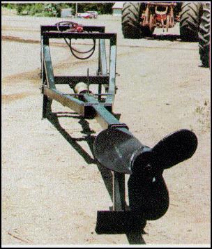
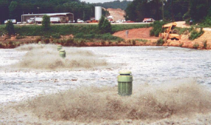
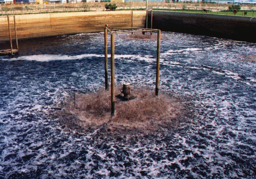
High - speed aerator...

Low - speed aerator...

Since low - speed surface aerators oxygenate the liquid by pumping, the volume of liquid under aeration is an important consideration. This relationship is usually expressed as horsepower per thousand gallons of volume. To illustrate this point, performance data for several types of surface aerators in water are presented in figures given below.


The average ranges of horsepower per thousand gallons ( hp / 1,000 gal ) are shown in figure given below for the activated sludge process, the extended aeration process, and for aerated lagoons.

Example - 3...

A surface aeration system is to be employed to satisfy an oxygen demand of 12,000 lb / day in an activated sludge plant. If a manufacturer states that a particular type of aerator will provide 3.0 lb O 2 / hp . hr at standard conditions, determine the total horsepower requirement for this system. System design is to be based on an ambient air temperature of 75 O F, a prevailing pressure of 0.95 atm, an ALPHA value of 0.80, a dissolved solids concentration in the liquid of 600 mg / L. The total aeration tank volume is 1.2 mgd.

Solution...

( 1 ) Compute the oxygen saturation concentration at the liquid surface ;

From step 1a in " Example - 1 ", a value of 8.4 mg / L is determined.

( 2 ) Adjust the standard condition oxygen transfer rate to process conditions by assuming a residual DO of 2.0 mg / L.

( T.R. ) ACTUAL = ( 3.0 ) ( 0.8 ) [ ( 8.4 - 2.0 ) / ( 9.2 ) ] = 1.67 lb O 2 / hp . hr

( 3 ) Compute the total horsepower requirement for the aeration system.

Total hp = ( 12,000 lb / day ) / [ ( 1.67 lb O 2 / hp . hr ) ( 24 hr / day ) ] = 300

( 4 ) Compute the power level ( i.e., the horsepower input per 1,000 gal of aeration tank valume ) and check figure given above to ensure that the calculated value is a reasonable one for activated sludge plants.

PL = ( 300 ) / ( 1,200 ) = 0.25

According to figure given above, this is a typical value for activated sludge.

Mixing Considerations...

Mixing is also an important consideration in the design of aeration systems. Good mixing is required to maintain the biomass in suspension as well as to distribute oxygen throughout the liquid volume. However, the degree of mixing required for oxygen dispersion is considerably less than that required complete mixing. For a specific power input this means that the zone of oxygen dispersion will be larger than the zone complete mixing. Such performance data are given in table shown below.

Hp Transfer rate at standard conditions
( lb O 2 / hp . hr )
Zone of complete mixing
( ft )
Depth
( ft )
Zone of complete oxygen dispersion
( ft )
Pumping rate through unit
( gpm )
20 3.2 72 10 230 8,320
25 3.4 80 10 255 9,830
30 3.5 88 10 280 12,570
40 3.8 102 10 325 14,000
50 3.5 105 12 330 18,560
60 3.5 115 12 350 20,560
75 3.0 130 12 380 22,550
100 3.1 150 12 440 41,000
125 3.3 165 12 490 47,500
150 3.2 185 12 530 57,000

Since all aerators are low - head pumps, miixing can be related to pumping capacity. " Busch " reports that the pumping capacity of a submerged turbine aerator is between 1 and 10 cfs / hp,whereas the pumping capacity for diffused aeration and low - speed surface aeration is 4.7 and 4.5 cfs / hp, respectively. These values can be used to compute the theoretical turnover time for a given volume. " Shell " and " Cassady " suggest that a turnover time of 7.5 min or less is generally sufficient for complete mixing if the system is well baffled.

Example - 4...

For the surface aeration system described in " Example - 3 ", the manufacturer has furnished a pumping capacity figure of 4.5 cfs / hp. For this system, determine the theoretical turnover time. Is the resulting value within the range for complete mixing ?

Solution...

Turnover time = ( 1,200,000 gal ) / [ ( 4.5 ft 3 / sec . hp ) ( 0.25 hp / 10 3 gal ) ( 1,200 10 3 ) ( 60 sec / min ) ( 7.5 gal / ft 3 ) ] = 2 min

The turnover time is less than 7.5 min ; therefore, complete mixing should occur.