This chapter includes some pics related to explanatory tables in accordance with
the subject...
For a faster connecting, in the other words, for your convenience, pics and tables were marked by
the icon

instead of themselves... You will find the content of the pics and
tables just after this icon...
To access the pics and table you want, just click on the explanatory item coloured
in red...
In addition, all the other pics have thumbnails... Just click on them for larger size...
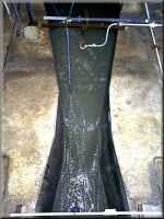
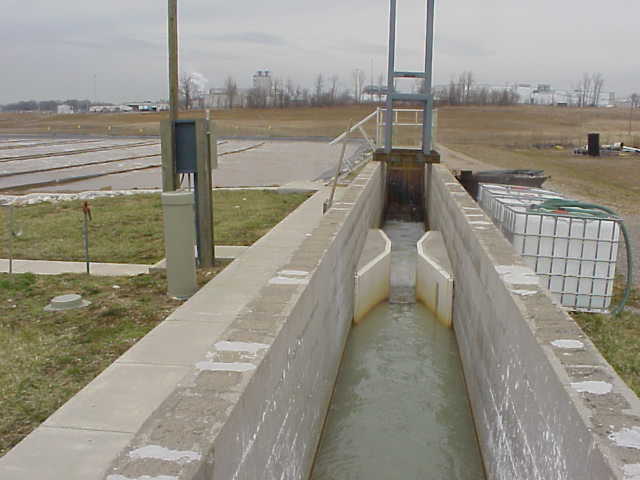
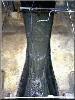
"Parshall Flume - 1"...
What is a "Parshall Flume" and Who Invented It ?...
A Parshall flume has a special shaped open channel flow section which may be installed in a ditch ,canal, or lateral to measure the flow rate. The Parshall flume is a particular form of venturi flume and is named for its principal developer,
the late Mr. Ralph L. Parshall (Water Measurement Manual, U.S. Bureau of Reclamation, 1984)." Ralph L. Parshall saw
problems with stream measurements when he began working for the USDA in 1915, as an irrigation research engineer. In
1922 he invented the flume now known by his name. When this flume is placed in a channel, flow is uniquely related to
the water depth. By 1953 Parshall had developed the depth-flow relationships for flumes with throat widths from 3 inches
to 50 feet. The Parshall flume has had a major influence on the equitable distribution and proper management of irrigation water.
Introduction...
Our Parshall flume calculation is based on the ISO 9826 (1992) standard. The standard is valid for submerged as well as free-flowing Parshall flumes. A free flowing flume can be identified by the drop in water depth at the flume throat. In submerged flow, the downstream water backs up into the throat swallowing the drop making the drop difficult or impossible
to identify. Analysis of submerged flow requires two head measurements - one in the approach channel and one in the
throat. Whereas, free flow requires only the upstream head measurement.

Parshall flumes must be built with their dimensions in strict accordance with specifications in published documents such
as the ISO 9826 and ASTM D1941 (1991) standards or USBR (1997). Flumes (like weirs) are designed to force a transition
from sub-critical to super-critical flow. In the case of Parshall flumes, the transition is caused by designing flumes
to have a narrowing at the throat and a drop in the channel bottom. Such a transition causes flow to pass through critical depth in the flume throat. At the critical depth, energy is minimized and there is a direct relationship between water
depth and velocity (and flowrate). However, it is physically very difficult to measure critical depth in a flume because
its exact location is difficult to determine and may vary with flowrate. Through mass conservation, the upstream depth is related to the critical depth. Therefore, flowrate can be determined by measuring the upstream depth, which is a highly reliable measurement. Like all of LMNO Engineering's software, our Parshall flume calculation was written in double precision.
Equations and Methodology...
The methodology for our Parshall flume calculation follows that of ISO 9826 (1992). ASTM D 1941 (1991) also addresses Parshall flumes but has pages of tabular data which are more difficult to implement into a computer program compared to
the figures and equations of ISO 9826.
Validity...
LMNO Engineering calculation allows 0<=h<=3 m and 0.010.152 m, C and n values are from ISO 9826 (1992), equations 10 and 11.
Free Flow...
Free flow occurs when a hydraulic jump is visible at the throat; that is, when the downstream head is significantly less
than the upstream head. Our calculation defines free flow as occurring when H/h<=0.6 for b<3.05 m or when H/h<=0.8 for b>=3.05 m. These criteria (called "modular limits") are similar, but not identical, to the ISO 9826 criteria. For free
flow ;
Q = ( C ) ( h n )
Where ; Q is flowrate in m 3 / sec and h is in m.
Submerged Flow...
Submerged flow occurs when a hydraulic jump is not visible at the throat; that is, when the downstream head is
sufficiently high that it "drowns out" or "swallows up" the hydraulic jump. In our calculation, submerged flow
occurs when H/h>0.6 for b<3.05 m and when H/h>0.8 for b>=3.05 m. For submerged flow, ISO equation 12 is re-written
as :
Q = ( C ) ( h n ) - QE
"Parshall Flume Coefficients"...
Where ; C and n are found from the above figure based on width (b). QE accounts for the effects of
submergence.
For b<3.05 m, ISO 9826 equation 13 provides the following equation for QE which is implemented in our
calculation :
For b>=3.05 m : QE = ( CS ) ( Q3 )
"Q3 Submerged Parshall Flume"...
CS = ( 0.3281 ) ( b ). ISO 9826 Figure 2 is a graph of Q3 as a function of H/h and h. LMNO
Engineering fit equations to all of the lines in the ISO figure for use in our calculation. A graph using our equations
for selected H/h ratios is shown :
"QE Equation"...
"Graph of Q vs. H/h, for b=0.5 m and h=0.5 m"...
The discharge for H/h<0.6 does not appear to be shown. However, our software scales the y-axis based on the maximum value
on the curve. In this case, the maximum value on the curve is 0.398 m 3 / sec which blends in with the boxed outline of the graph. The flow is 0.398 m 3 / sec for all H/h <0.6.
Comparison of ISO and ASTM Methods...
Both ISO 9826 and ASTM D1941 present methods for computing discharge through Parshall flumes. Since a Parshall flume
is a standard flume, the two methods should be similar. Looking at the two standards, they at first appear somewhat different because ISO 9826 is in SI units while ASTM D1941 uses predominantly English units. Further, the ISO standard presents information in tables, equations, and figures while ASTM D1941 uses tables almost exclusively. Curious as to
how well the two methods compare, we developed the following table. We also have done other comparisons but, due to
space considerations, have chosen not to show the results on this web page. In general, there is good agreement for free
flow, but in some cases the submerged flowrates are significantly different, such as for the b=0.152 case shown below.
Variables...
ISO 9826 specifies the indicated units for the equations shown above. Our calculation allows you to specify a variety of units.
"Comparison of ISO and ASTM Methods"...
b=Throat width [m].
C=Parshall flume constant [empirical units].
CS=Submergence coefficient [unit-less]. This is not the submergence ratio.
h=Measured upstream head [m].
H=Measured downstream head [m]. Only needed if the flume is submerged, or to determine mathematically if the flume is submerged. Usually, one can visually see if there is a hydraulic jump, but determining the ratio H/h is a quantitative method.
H/h=Submergence ratio. Flume is submerged if H/h>0.6 for b<3.05m or if H/h>0.8 for b>=3.05 m.
n=Parshall flume power constant [unit-less].
Q=Flowrate (discharge) through flume [m 3 / sec].
QE=Reduction in flowrate due to submergence [m 3 / sec].
Q3=Flow factor for determining QE if b>=3.05 m [m 3 / sec].