This chapter includes some pics related to explanatory tables in accordance with
the subject...
For a faster connecting, in the other words, for your convenience, pics and tables were marked by
the icon

instead of themselves... You will find the content of the pics and
tables just after this icon...
To access the pics and table you want, just click on the explanatory item coloured
in red...
In addition, all the other pics have thumbnails... Just click on them for larger size...
Weirs for Open-Channel Flow Measurement...
Effective use of water for crop irrigation requires that flow rates and volumes be measured and expressed quantitatively. Measurement of flow rates in open channels is difficult because of nonuniform channel dimensions and variations in
velocities across the channel. Weirs allow water to be routed through a structure of known dimensions, permitting flow
rates to be measured as a function of depth of flow through the structure. Thus, one of the simplest and most accurate methods of measuring water flow in open channels is by the use of weirs. In its simplest form, a weir consists of a
bulkhead of timber, metal, or concrete with an opening of fixed dimensions cut in its top edge. This opening is called
the weir notch; its bottom edge is the weir crest; and the depth of flow over the crest (measured at a specified distance upstream from the bulkhead) is called the head (H). The overflowing sheet of water is known as the nappe.
Types of Weirs ...
Two types of weirs exist: sharp-crested weirs and broad-crested weirs. Only sharp-crested weirs are described here because they are normally the only type used in the measurement of irrigation water. The sharp edge in the crest causes the water
to spring clear of the crest, and thus accurate measurements can be made. Broad-crested weirs are commonly incorporated in hydraulic structures of various types and, although sometimes used to measure water flow, this is usually a secondary function. The components of a sharp-crested weir are shown in Figure 1.
"Figure - 1"...
The most common types of sharp-crested weirs are rectangular, trapezoidal (Cipolletti), and 90 O V-notch weirs. These are shown in Figure 2.
"Figure - 2"...
The weir selected should be that most adapted to the circumstances and conditions at the sites of measurement. Usually,
the rate of flow expected can be roughly estimated in advance and used to select both the type of weir to be used and the dimensions of the weir. The following facts should be considered when a specific type of weir is selected for a given application. The head should be no less than 0.2 feet and no greater than 2.0 feet for the expected rate of flow. For the rectangular and Cipolletti weirs, the head should not exceed one-third of the weir length. Weir length should be selected
so that the head for design discharge will be near the maximum, subject to the limitations in 1 and 2. Measurements made
by means of a weir are accurate only when the weir is properly set, and when the head is read at a point some distance upstream from the crest, so that the reading will not be affected by the downward curve of the water. That distance should
be at least 4H. The proper method of measuring H is shown in Figure 1.
Rectangular-Notch Weir...
The rectangular-notch weir is illustrated in Figure 3. This is the oldest type of weir now in use. Its simple construction makes it the most popular.
"Figure - 3"...
The discharge equation for the rectangular-notch weir is :
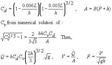
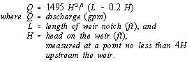
Equation 1 gives discharge values for rectangular-weir notch lengths of up to 4 feet and depths of flow or head of up to
1.5 feet.
 Cipolletti Weir...
The Cipolletti weir, illustrated in Figure 4, is trapezoidal in shape. The slope of the sides, inclined outwardly from the crest, should be one horizontal to four vertical.
"Figure - 4"...
The formula generally accepted for computing the discharge through Cipolletti weirs is :
Equation 2 where parameters are as defined in equation 1. The selected length of notch (L) should be at least 3H and preferably 4H or longer. Discharge values for Cipolletti weir notch lengths of up to 4 feet and depths of flow up to
1.5 feet are given in Table 1.
"Table - 1"...
 90 O V-Notch Weir...
The 90 O V-notch weir, Figure 5 , is most accurate when measuring discharges of less than 500 gpm. The
maximum discharge that can be accurately measured is approximately 5,000 gpm. The sides of the notch are inclined
outwardly at 45 O from the vertical.
"Figure - 5"...
The basic formula for discharge through the 90 O V-notch weir is :
Equation 3, where H = vertical distance (ft) between the elevation of the vertex (lowest part of the notch) and the
water surface at least 4H upstream from the weir, and other parameters are as previously defined. Table 2 gives
discharge values for 90 O V-notch weirs for heads up to 1.5 feet.
"Table - 2"...
 Construction and Placement...
The following general rules should be observed in the construction and installation of weirs. A weir should be set at
right angles to the direction of flow in a channel that is straight for a distance upstream from the weir at least ten
times the length of the weir crest. The crest and sides of the weir should be straight and sharp-edged. The crest of the rectangular and Cipolletti weirs should be level and the sides should be constructed at exactly the proper angle with the crest. Each side of the V-notch weir should make a 45 ° angle with a vertical line through the vertex of the notch. The channel upstream should be large enough to allow the water to approach the weir in a smooth stream, free from eddies, and with a mean velocity not exceeding 0.3 foot per second. Avoid restrictions in the channel below the weir that would cause submergence. The crest must be placed higher than the maximum downstream water surface to allow air to enter below the
nappe.
Construction and Placement...
The following general rules should be observed in the construction and installation of weirs. A weir should be set at
right angles to the direction of flow in a channel that is straight for a distance upstream from the weir at least ten
times the length of the weir crest. The crest and sides of the weir should be straight and sharp-edged. The crest of the rectangular and Cipolletti weirs should be level and the sides should be constructed at exactly the proper angle with the crest. Each side of the V-notch weir should make a 45 ° angle with a vertical line through the vertex of the notch. The channel upstream should be large enough to allow the water to approach the weir in a smooth stream, free from eddies, and with a mean velocity not exceeding 0.3 foot per second. Avoid restrictions in the channel below the weir that would cause submergence. The crest must be placed higher than the maximum downstream water surface to allow air to enter below the
nappe.
