Pumping Stations...
 "Design of Pumping Stations - 1 ( In Turkish )"...
"Design of Pumping Stations - 2 ( In Turkish )"...
"Design of Pumping Stations - 3 ( In Turkish )"...
( Alanya Marine Outfall System... )
"Design of Pumping Stations - 4 ( In English )"... 
Station Capacity...
Pumping station capacity requirements are normally determined by the hydraulics engineer in accordance with EM 1110-2-1413.
This manual provides the basis for establishing pumping requirements for the maximum and minimum river stages, and the
maximum water stages permissible in the protected area. The latter will be referred to the station location and will
establish the maximum allowable water surface elevation in the station sump. The hydraulic data provides the basic
information needed for the selection of equipment and, in turn, the layout of the station. In those special instances
where an increase in pumping capacity can be definitely expected at some future date, consideration should be given to
a station design which facilitates the installation of increased capacity in a manner that will give the greatest overall
economy. Alternate studies of pumping stations satisfying the required pumping capacity should be made for all pumping
station projects. As a minimum, the studies should include station location, station site layout, all equipment, sizing
of pumps, type of operation, and oper-ating and maintenance costs and first costs.
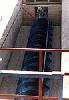

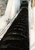
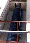
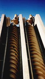
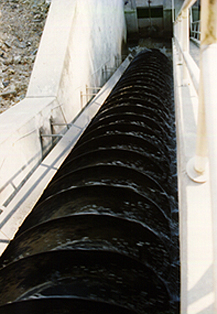
"Archimedian screw pumps..."
Station Location...
General : Experience has shown that a pumping station should be located or sited in such a manner to produce the
most direct inflow possible. Any location that produces asymmetrical flow into the pump bays causes problems with
circulation, uneven velocity distribution, vortices, and generally poor pump performance. This is true for inflow
confined within an inlet channel, sewer, or a large ponding area. Additional engineering studies and/or physical modeling
may be required when circumstances exist that prevent recommended station siting. Gravity flow structures, when provided,
can be located in an offset position without additional cost and still perform adequately.
Line of protection : The location of stations with respect to the line of protection should be selected for safe
operation. Construction of the station integral with a concrete floodwall will, in general, minimize the hazard of
discharge line failure. On projects with an earth levee or where right-of-way restrictions exist, the station may be
located at the landside toe of the levee. More hazardous locations (riverside of protective works) may be considered if
a definite operational or economic advantage is presented. Vehicle access to stations at all flood elevations should be
carefully considered in station location, and minimum but adequate provision should be made to permit safe operation of
service vehicles bringing in equipment during construction and operation and maintenance.
Operating floor elevation : The operating floor elevation should reduce the possibility of damage, caused by
flooding, to the pumping equipment. This elevation is dependent upon the hydraulics and hydrology criteria, the location,
and the physical layout of the pumping station. (1) When the pumping station is located on the line of protection, the
elevation of the operating floor will depend on whether the pumping station is subject to the discharge pool elevations,
or is protected by a flood wall or a discharge chamber. When the pumping station is subject to the discharge pool
elevations, the operating floor should be no lower than the top of the levee. When the pumping station is protected by
a flood wall or a discharge chamber, the operating floor elevation should be located at least 0.3 m (1 ft) above the
interior level of design protection. (2) When the pumping station is not located on the line of protection, the elevation
of the operating floor should be at least 0.3 m (1 ft) above the interior level of design protection. (3) For high,
nonpumping water levels, one method to reduce the operating floor elevation is to floodproof the facility. Floodproofing
would be achieved by providing watertight doors or bulkheads at all openings. If flood-proofing is being considered, the
cost and practicality to floodproof the facility should be carefully studied.
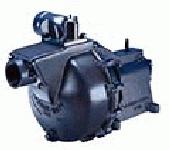
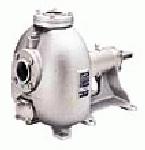
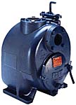
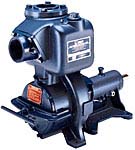
Station Type...
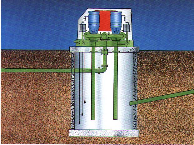
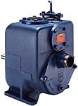
Floodwater pumping stations : These stations should be of the wet-pit (sump) type employing vertical mixed-flow or
axial-flow pumps in practically all cases. These pumping units may also be of the submersible type (Plate 1). Floodwater
pumping stations usually pump directly from open storage ponds, ditches, or stormwater sewers. When practical, provision
should be made for exclusion of water from the pump sump and for maintaining the sump in a dry condition during inoperative
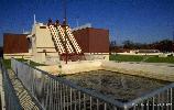
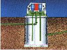
periods. A typical station for pumping water from an extensive open ponding area is shown in Plates 2 and 3. This station
is located at the edge of the ponding area, adjacent to the gravity drainage structure discharging through the levee. The
station's inlet sump is at an elevation considerably lower than the gravity flow stream requiring the sump to be pumped
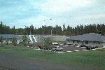
dry when the station is not in use. A large pumping station that pumps from an open sump is shown in Plates 4 and 5. A
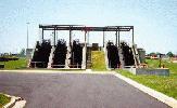
typical storm-water pumping station that pumps from a stormwater sewer is shown in Plates 6 and 7. Occasionally stations
will be located over streams or drainage canals and in such instances pumps must be protected from damage by runoff during
inoperative periods. Since the liquids pumped by stormwater pumping stations are generally not of a particularly corrosive
nature, a wider latitude in selection of materials is permitted.
Combination flow pumping stations : Stations in which flows consist of some combination of stormwater and domestic
and industrial wastes are characterized by having to pump runoff containing undiluted waste. The possibility of fumes and
vapors should be considered when designing the sump ventilation system and electrical features located in the sump. When
wastes are combined with stormwater, the need for a smaller pump to handle dry weather flows and runoff from light rains
should be provided. This baseflow pump should be a submersible, nonclog pump. The baseflow pump is located in the main sump
and equipped so that it can be raised for cleaning or repair, reducing the need for personnel to enter the sump. For
stations on sewers having a relatively short time of concentration, it is necessary to place the stormwater pumps in
operation within a short time after the start of rainfall. If large sluice gates are used to close the opening between
forebay and the main sump, power operation of the gates will be required. Diluted domestic and indus-trial wastes will be
present in the main sump. Protection against corrosive fumes and vapors is a greater problem than in stations handling only
stormwater. All sump openings in the superstructure should be sealed airtight.
Sump Design...
General : Rectangular wet pit and the formed suction intake (FSI) are the two basic sump types most commonly used
in civil works pumping stations. (a) Rectangular wet pit : In the past, the rectangular wet-pit sump with the
conventional pump bell-mouth inlet was the most common type used. Experience has shown, however, that the sump's hydraulic
performance is very sensitive to inflow conditions, sump design, and pump operation. (b) FSI : The FSI was developed
in the early 1990's by the WES Hydraulics Laboratory. The FSI has demonstrated the ability to improve the poor hydraulic
sump performance sometimes experienced with the rectangular wet-pit sump.
Size and Capacity Determination : (a) Sump levels : Maximum water surface elevation in the sump of stations
pumping from sewers will be fixed by project damage elevation, by the hydraulic gradient between the protected area and the
pumping station, and by the condition of the particular sewer. For stations pumping from ponding areas, the maximum water
surface elevation of the sump will be fixed by the maximum permissible ponding elevation. For sewers subject to structural
damage from fluctuating water pressure, such as old brick sewers in questionable condition, and sewers which are inadequate
to pass the design storm runoff, the maximum sump operating level should be restricted to the elevation of the crown of the
sewer at the point of entrance to the sump. For a well-designed and well-constructed sewer, the maximum sump operating
level may fall above the crown of the sewer, subject to consideration of the level of the hydraulic gradient with respect
to "no damage" level along the sewer. The station-operating floor elevation should be no lower than 1 ft above the maximum
water surface elevation in the sump. The sump shall be kept dry either by gravity drainage or by sump pump(s). If the
period of gravity drainage occurs less than 50 percent of the nonpumping period, then sump pumps should be provided to
dewater the station's sump. The minimum water surface elevation in the sump is determined by the hydraulic and protection
requirements of the protected area and economic con-siderations. This minimum sump elevation affects the station design and
pumping equipment characteristics. (b) Minimum sump area : Minimum horizontal sump area will be that required to
permit adequate spacing of pumps and intake systems to provide adequate space for installation of discharge and suction
lines and associated equipment and flows to the pumps. Sump area based on these requirements normally will be adequate
unless it is found desirable to increase the horizontal area of the sump either to provide more sump storage volume to
obtain acceptable minimum pump operating cycles, or to alleviate surges caused by pump shutdown in the sump and connecting
sewers. (c) Determination of sump dimensions : The dimensions and general layout of the sump must fulfill a number
of requirements. Primarily, the selected design must provide adequate horizontal and vertical clearance and adequate
approach conditions for the pumps to be used. Important layout and dimensional requirements for satisfactory pump
performance are as follows : (1) Horizontal clearances for rectangular wet-pit sumps are generally satisfied if the
distance between centerlines of adjacent pumps is equal to the sum of the suction bell diameters (plus the thickness of
the divider wall), and if the centerline of each pump is a least one suction bell diameter away from the nearest sump side
wall and three-fourths of a suction bell diameter from the rear wall. The use of suction umbrellas does not change the
above clearances. In general, the diameter of a propeller pump's suction bell (no umbrella) is around 1.5 to 1.6 times
the nozzle inlet diameter. (2) The principal factors involved in the determination of submergence and vertical clearance
requirements are cavitation limits and the means to preclude the formation of sustained vortices. (3) Cavitation can be
reasonably predicted from the computational procedure. This procedure computes the required submergence based on test
results of pumps at Corps pumping stations. A submergence allowance is used to obtain greater submergence for pumping
stations with long periods of operation. The impeller should always be completely submerged at the start of pumping. (4)
Vortex formation can be minimized by controlling the flow conditions into the sump and to the pump. If the station cannot
be laid out to these dimensions and straight inflow does not occur, then either a sump model test should be considered or
the FSI incorporated into the design. The FSI has demonstrated the ability to nearly eliminate vortexing at the pump.
(d) Sump layout : (1) The best flow conditions are obtained when the water approaches the pump from all directions
with as uniform a velocity as possible and with minimum disturbance from the flow toward other units. The placing of the
sump intake to provide as near equal flow distances as possible to the pumps is a good start toward satisfactory sump flow
conditions. (2) Whenever station layout permits, an intake gate should be provided in front of each pump. Velocity through
intake gates must be coordinated with the sump drawdown or operating range. In general, the velocity through intake gates
should be as low as possible provided no special requirements or excessive increased costs are involved. In no case should
the velocity through the gate be greater than 1.5 m/sec (5 fps). Abrupt changes in direction and velocity of flow should be
avoided. (3) Sump design and layout will be based on estab-lished Corps guidance. However, if the pump manufacturer
disagrees with the Corps' design and proves, through model testing, a better design, then the contractor's design should
be used and the contractor held responsible for the sump design. (e) Sump capacity : (1) In addition to the
above-mentioned requirements for satisfactory pump operation, the station design should include a determination of the
water volume between maximum and minimum operating elevations that will permit acceptable minimum pump operating cycles.
This water volume would include the capacity of the sump, trash rack chamber, interconnecting sewer, or ponding area.
Sufficient storage is provided between the pump's starting and stopping elevations when the starting of any one pump will
not be required more often than once in 15 min or a cycle as recommended by the motor manufacturer. An inflow rate equal
to one-half of the pumping rate of the pump should be assumed, as this inflow will cause the most frequent number of
repeated starts and stops of the pump. Storage required above the stop elevation to ensure a minimum interval as indicated
above between successive starts of a given pump is usually not possible. Since the maximum sump operating level is usually
fixed by the project damage elevation or other considerations, any required increase in sump capacity can be accomplished
only by lowering the sump floor. A gain in sump capacity by lowering the sump floor is usually attended by increased pumping
power requirements. An increase in sump area will probably cause adverse flow to pumps and therefore cannot be used. A
variable speed pump drive should be considered since on-off cycles and surges when the unit is stopped can be eliminated
by its use. (2) The use of bypasses gains equivalent sump capacity during periods of pump operation with small inflows and
accomplishes that function by decreasing the net effective discharge of pumps operating. Bypasses should be considered where
space and structural requirements cannot be changed and sump capacity is inadequate to: prevent excessively frequent starting
of pumps, particularly where failure of one pump of a group operated on programmed control is a possibility; compensate for
a lag in the inflow from a sewer; and prevent surges in sewers and sumps which would be caused by rapid lowering and then
raising of sump levels. (3) Bypasses may be located so as to permit return flow from riverside discharge chambers into the
sump, or direct flow from a pump discharge line into the sump at a point between the pump and its discharge. With the former
arrangement, the bypass is effective regardless of which pump is operated. The latter arrangement is used where pump
discharge lines pass over levees and require a bypass on each pump or a number of pumps to ensure satisfactory bypass
capacity when any pump is out of service. (4) Where a single bypass from the discharge chamber to the sump is to be
installed, its capacity at minimum head and maximum operating sump water elevations should be at least equal to the
capacity of the largest incremental change in discharge capacity. When a bypass is located on a pump discharge line,
its capacity under the same conditions of head should be sufficient to provide the desired operating cycle, usually
one-half the capacity of the largest pump. In both cases, the increased capacity of pumps at lower than design heads
should be recognized. Butterfly valves are normally used to control the bypass flow. These valves are provided with power
operators when manual operation requires more then a 110-N (25-lb) pull on the valve operator. (5) The determination of
sump capacity requires close coordination with the entire design of the pumping station. Basic factors such as type of
prime mover, number and size of pumps, and size and arrangement of station are affected by, or have an effect on, sump
capacity. Selection of design to provide adequate sump capacity should be based on a comparison of overall cost for each
installation. Factors to be considered include cost of sump structure and superstructure, higher price of equipment
accompanying any increase in pumping requirements, increased cost of variable-capacity in lieu of fixed-capacity pumps,
and cost of operation.
Surges in Sump...
General : Surges may occur in pipelines which flow full and are subject to sudden changes in rate of discharge.
This is possible where the sump area and adjacent areas have too small a water volume. Serious damage could occur if proper
consideration is not given to the effects of surges in designing the pump station. Surges and resulting rapid fluctuations
of the water surface elevations in the sump could also affect the proper operation of the automatic stop controls of the
pump. The condition of a surcharged pipeline discharging to a pump station sump may be considered somewhat analogous to
the penstock and surge tank of a hydroelectric powerplant. HDC should be consulted under these conditions.
Amount of surge : The height to which the water will surge in the pump sump is a function of the length of a
pipeline flowing full, the cross-sectional area of the pipeline, the volume of the sump, the change in pump discharge,
and the friction losses. An exact mathematical solution of the problem is often practically impossible because of the
many changes in pipe size and the numerous inlet points on a sewer system. However, approximate methods, developed by
HDC, permit mathematical treatment of the problem and give results sufficiently accurate for design purposes.
Provisions for protection against surge : Certain features inherent in the design of pumping stations and sewer
systems automatically supply a dampening effect on surges. Various laterals and manholes of the sewer system, the
operating sump, and intake and trash rack wells act as surge tanks. Use of adjustable-blade pumps or variable-speed
motors will allow gradual reduction of pump discharge upon shutdown and would reduce operational difficulties arising
from surges. In cases where the surge will be great, consideration of one of the following methods will aid in solving
the problem. (1) Raise the operating floor of the pumping station above ground level and provide overflow openings below
the station floor. In order to confine the effluent and facilitate its removal, a catch basin would have to be constructed
adjacent to the forebay, with a gravity drain to return the overflow to the station. This method would protect the station
from damage due to extremely large surges that might be caused by total station shutdown, but ordinarily would not alleviate
the smaller surges due to shutdown of single pumps, which may cause operational difficulties. (2) Stations having the operating
floor above the high-water elevation or located outside the line of protection may have flap-gated bypasses from the station
sump pump intake to a pressure discharge chamber or directly into the stream. This arrangement might require changes in the
station design, particularly in the design of the operating floor which may be subject to upward pressures. This method can
be used to protect the station from extremely large surges. The effectiveness of the method in reducing smaller surges
would be dependent upon the elevation of the water surface in the discharge chamber or in the stream at the start of the
surge and upon the elevation at which the bypasses are placed. (3) The horizontal cross-sectional area of the inflow sump
could be increased to act as a surge tank. The sump dimensions should not be increased above that area required for proper
sump flow. (4) A special surge tank or a surge basin could be used at some point on the pipeline near the pumping station.
The effectiveness of this method is dependent upon the horizonal cross-sectional area provided by the eleva-tion at which
the surge tank becomes effective. This method is effective in reducing all surges, both in the sump and in the connecting
sewer. However, for greatest effect at the pumping station, the surge tank or surge basin should be placed as close to the
station as practicable. (5) For a large pipeline, an initial intake sump could be provided with a regulating weir into a
second sump at one side in order to maintain a constant hydraulic gradient in the sewer. This method would prevent surges
from moderate changes in pump discharge but may not greatly affect large surges resulting from total station shutdown and
may not afford sufficient protection for the pumping station.
Trash Racks...
Racks : Except for stations of minor importance and sewage-type pumping stations, all flows into flood protection
pumping stations should be screened before reaching the pumps. Conventional bar screens (trash racks) are the preferred
method of screening. Suction strainers should be avoided as they clog readily and are difficult to clean. Trash racks must
be located to allow incoming flows to pass through the rack before reaching any pump intake, flow to be evenly distributed
over the submerged rack surface, and raking to be accomplished coincident with pump operation. Trash racks located in the
sewer which flows by the pumping station should be readily removable, and minimal means should be provided to allow the
racks to be raised above the maximum sump level and secured when the station is not in use. Trash racks should always be
located outside the station super-structure in order that operating areas are not exposed to the moisture and fumes usually
present during raking operations, and to facilitate disposal of trash accumulations. Where flows are adequately screened
prior to entry into the collecting system by grated catch basins or other methods, trash racks need not always be provided.
However, omission of trash racks must be based upon sound engineering judgment and economic considerations and must be
justified and explained in the design analysis.
Effective areas and bar spacing : Trash racks should have ample net area so that the velocity of the flow through
the gross rack area does not exceed 0.76 m / sec (2.5 fps). The clear opening between bars should be approximately 45 mm
(1-3/4 in.), but may be greater if justified by the size and type of pumps to be protected, but should not exceed 75 mm
(3 in.) in any case. Bar spacing should be coordinated with the pump manufacturer.