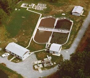
Oxidation Ditch...
Double Oxidation Ditch...
The Double Ditch (D-Ditch) mode of Phased Isolation Ditch (PID) technology is a completely self-contained treatment process.
The D-Ditch Process consistently produces a fully nitrified effluent, low in BOD and suspended solids, without the use of
clarifiers. D-Ditch plants are often compared to Sequential Batch Reactors (SBR) because they operate without an external
clarifier. However, the D-Ditch Process offers several features that increase process stability and decrease operating
complexity when compared to SBR's. These features include a constant water level and continuous discharge which lower the
surface settling rate, lower the weir overflow rate, optimize the aeration unit process, and eliminate the periodic surges
of effluent associated with SBR's.
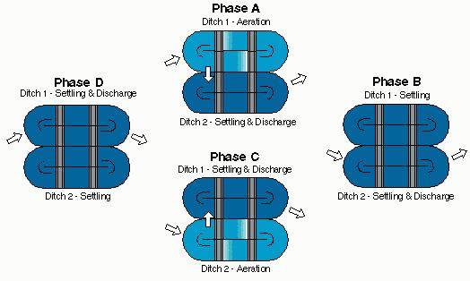
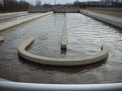
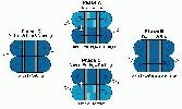
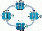
The D-Ditch Process operating cycle consists of two main phases (A & C), and two intermediate phases (B & D). As shown in
the operating cycle schematic Phases C & D are mirror images of Phases A & B. During Phase A, the influent is directed to
the ditch that is under aeration (Ditch 1). The rotors aerate the mixed liquor, resulting in degradation of the influent
BOD and nitrification of ammonia-nitrogen. The rotors are idle in Ditch 2, which is serving as a clarifier. The mixed
liquor flows from Ditch 1 to Ditch 2 because the ditches are hydraulically interconnected by a port in the common wall,
and the effluent weir in Ditch 2 is lowered to allow treated and clarified effluent to be discharged. During Phase B, the
influent is redirected to discharge to Ditch 2, which continues to operate in the settling and discharge mode. The duration
of Phase B is relatively short, and the volume of influent received during Phase B is small in comparison to the volume of
Ditch 2. Therefore, the influent has little effect on the treated effluent being discharged. Ditch 1 is isolated. The rotors
in Ditch 1 are idle in Phase B to allow the sludge blanket to drop in preparation for Phase C, when Ditch 1 will begin
discharging effluent. Phase C is initiated by raising the effluent weir in ditch 2, and lowering the effluent weir in Ditch
1. The rotors are activated in Ditch 2, which continues to receive influent. The hydraulic gradient through the ditches has
been reversed. Ditch 1 serves as a clarifier settling solids and discharging treated effluent. The D-Ditch can easily be
expanded and upgraded by either adding another oxidation ditch and operating the Triple ditch Process, or by adding clarifiers
and operating in the BioDenitro Process.
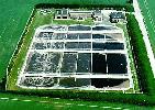
 Triple Oxidation Ditch...
The Triple Ditch (T-Ditch) mode of PID technology is an expansion and upgrade of the double ditch process that efficiently
performs controlled nitrogen removal without an internal recycle stream or external clarifiers. The T-Ditch Process, the
three hydraulically-interconnected oxidation ditches alternatively serve as oxic, anoxic, or quiescent reactors, performing
nitrification, denitrification, and clarification respectively. Because of the flow direction through the oxidation ditches
is periodically reversed, RAS pumping, and internal recycle streams are not required. The T-Ditch Process can be designed
for secondary treatment with full nitrification, or for nitrogen removal using the BioDenitro Process adapted to the T-Ditch
layout. The BioDenitro Process is described in detail in the following section.
Triple Oxidation Ditch...
The Triple Ditch (T-Ditch) mode of PID technology is an expansion and upgrade of the double ditch process that efficiently
performs controlled nitrogen removal without an internal recycle stream or external clarifiers. The T-Ditch Process, the
three hydraulically-interconnected oxidation ditches alternatively serve as oxic, anoxic, or quiescent reactors, performing
nitrification, denitrification, and clarification respectively. Because of the flow direction through the oxidation ditches
is periodically reversed, RAS pumping, and internal recycle streams are not required. The T-Ditch Process can be designed
for secondary treatment with full nitrification, or for nitrogen removal using the BioDenitro Process adapted to the T-Ditch
layout. The BioDenitro Process is described in detail in the following section.
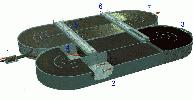
The T-Ditch is equipped with the simple influent and effluent hydraulic controls typical of all PID systems. During the main
phases, influent is directed to one of the outer ditches forcing mixed liquor through the center ditch to the other outer
ditch, which serves as a clarifier and discharges treated effluent. Influent flow diversion is controlled with three motor
operated weirs. Each weir trough discharges to one of the ditches. Depending on the status of the process, one weir will be
lowered while the other two weirs remain raised. The T-Ditch Process is the most energy efficient biological nitrogen removal
process available today. As with the Double Ditch Plants, Triple Ditch plants can easily be expanded by adding clarifiers.
Typically, clarifiers will increase the capacity of the plant by 50%, cost-effectively keeping pace with community growth.
 Bio-Denitro Oxidation Ditch...
The BioDenitro mode of PID Technology is an energy-efficient wastewater treatment process that consistently achieves high
levels of nitrogen removal without internal recycle pumping or chemical dosing. Since its' introduction in the 1976 US EPA
Nitrogen Control manual, more than 100 BioDenitro plants have been constructed worldwide. The 3.0 MGD Ocoee, Florida Plant
was the first of many US BioDenitro installations.
Bio-Denitro Oxidation Ditch...
The BioDenitro mode of PID Technology is an energy-efficient wastewater treatment process that consistently achieves high
levels of nitrogen removal without internal recycle pumping or chemical dosing. Since its' introduction in the 1976 US EPA
Nitrogen Control manual, more than 100 BioDenitro plants have been constructed worldwide. The 3.0 MGD Ocoee, Florida Plant
was the first of many US BioDenitro installations.
The BioDenitro Process was initially developed as an inexpensive method of treating wastewater in response to the 1970's
energy crisis. As a result, denitrification was included in the operating scheme from the onset as a means of reducing the
overall energy consumption. Oxidation ditches, including plants designed for nitrification, typically possess a considerable
amount of excess volume. The BioDenitro Process utilizes this excess volume for controlled anoxic denitrification within the
ditches in order to reduce the overall oxygen requirement. As a result, alkalinity lost in the nitrification process is
regained, stabalizing process conditions. Because the BioDenitro Process does not require separate anoxic reactors for
denitrification, it can easily be implemented at most existing oxidation ditch plants to reduce operating costs and
increase effluent quality.
Phased Isolation Ditch systems, such as the BioDenitro Process, consist of interconnected oxidation ditches which are
equipped with motor-operated influent and effluent controls, mixing equipment, and aeration equipment. The influent
distributor and effluent weirs associated with a Phased Isolation Ditch provide complete control over the flow pattern in
the BioDenitro process. For instance, in the main phases of the BioDenitro Process, the mixed liquor follows a series flow
pattern through the ditches. However, the series flow pattern in Phase C is a mirror image of the series flow pattern in
Phase A. The series flow pattern is initially produced by raising the effluent weir to impede the discharge of flow in the
ditch receiving influent (Ditch 1). The effluent weir in the adjacent ditch (Ditch 2) is lowered to allow flow to discharge.
Because the ditches are interconnected by an open port in the common wall, a hydraulic gradient is established that forces
the mixed liquor from Ditch 1 to Ditch 2. Reversing the flow pattern is a simple operation that involves raising or lowering
the effluent weirs, while redirecting the influent inflow via the influent distributor. In order to reverse the flow pattern,
the influent distributor redirects the forward flow to enter Ditch 2 instead of ditch 1. Simultaneously, the effluent weir
in Ditch 1 is lowered, while the effluent weir in Ditch 2 is raised to impede the discharge of effluent. This reversal of
flow direction is automatically controlled via PLC's or timers and occurs approximately every two hours.
 Method of Operation...
In most conventional treatment systems, nitrates are created in an oxic reactor and then transferred back to an anoxic
reactor to facilitate denitrification. In the BioDenitro Process, the oxidation ditches alternate between oxic (nitrification)
and anoxic (denitrification) phases. During oxic phases, influent ammonia-nitrogen (NH3 - N) is oxidized to produce
nitrate nitrogen (NO3 - N). During anoxic phases, influent BOD serves as the carbon source required to reduce the
nitrates to nitrogen gas, while submersible mixers maintain the biosolids is suspension. The BioDenitro Process operating
cycle includes two main phases and two intermediate phases. During the main phases of the process (Phase A and C), one ditch
will always operate in the anoxic (denitrification) mode while the other ditch operates in the oxic (nitrification) mode.
During the shorter duration intermediate phases of the process (Phase B & D), both ditches operate in the oxic mode.
Method of Operation...
In most conventional treatment systems, nitrates are created in an oxic reactor and then transferred back to an anoxic
reactor to facilitate denitrification. In the BioDenitro Process, the oxidation ditches alternate between oxic (nitrification)
and anoxic (denitrification) phases. During oxic phases, influent ammonia-nitrogen (NH3 - N) is oxidized to produce
nitrate nitrogen (NO3 - N). During anoxic phases, influent BOD serves as the carbon source required to reduce the
nitrates to nitrogen gas, while submersible mixers maintain the biosolids is suspension. The BioDenitro Process operating
cycle includes two main phases and two intermediate phases. During the main phases of the process (Phase A and C), one ditch
will always operate in the anoxic (denitrification) mode while the other ditch operates in the oxic (nitrification) mode.
During the shorter duration intermediate phases of the process (Phase B & D), both ditches operate in the oxic mode.
In Phase A (90 minutes), Ditch 1 is anoxic and nitrates produced during the previous three oxic phases in Ditch 1 are
denitrified. Influent BOD serves as the carbon source required to fuel the denitrification, while submersible mixers
maintain the biosolids in suspension. Ditch 2 is oxic, and discharges treated effluent to the clarifiers. In phase B
(30 minutes), both ditches are oxic. The influent is directed to Ditch 2, which continues to discharge treated effluent
to the clarifiers. In Phase B (30 minutes), both ditches are oxic. The influent is directed to Ditch 2, which continues
to discharge treated effluent to the clarifiers. Ditch 1 is isolated to allow nitrification of the ammonia that entered
the ditch during Phase A. In Phase C (90 minutes), the effluent weir in Ditch 2 is raised while the effluent weir in Ditch
1 is lowered. The rotors in Ditch 2 are deactivated, and the mixers are activated. Anoxic conditions are produced in Ditch
2 which causes nitrates, created during the previous 3 phases, to be reduced to nitrogen gas. Ditch 1 is oxic (nitrification)
and is discharging treated effluent to the clarifiers. Phase D (30 minutes) is another intermediate phase similar to Phase
B. At the end of this phase, the operating cycle will be complete and will be repeated, beginning with phase A. Typically 4
to 6 complete cycles will be performed over one hydraulic retention time. In addition, effluent is always discharged from an
oxic ditch to minimize the ammonia concentration discharged from the plant.
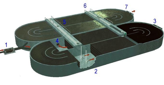
- The influent distributor is a motor-operated gate that changes position from left to right approximately every 2 hours.
In the phase of the BioDenitro operating cycle (above), the distributor is directing the influent and RAS to Ditch 2. This
supplies the required carbon source fro denitrification.
- Low-speed submersible mixers impart the velocity to amintain the biosolids in suspension during the anoxic phases of
the process. the mixers also supplement the rotors as
needed in response to automatic DO control during oxic phases of the process.
- The motor-operated effluent weir changes position from raised to lowered, or vice versa, approximately every 2 hours.
In this phase of the process, the weir in Ditch 2 is raised.
- Dentrified mixed liquor flows from Ditch 2 to Ditch 1 due to the hydraulic gradient set up by the influent distributor
and effluent weir.
- A probe monitors the Dissolved Oxygen concentration in the mixed liqour and transmits a signal to the control panel,
which controls the operation of the rotors via a custom programmed PLC.
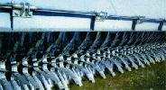
- Brush aerators (rotors) maintain oxic conditions within the mixed liquor during nitrification phases of the process.
The rotor bridge eliminates noise and aerosols, while providing access for equipment maintenance.
- The effluent weir in Ditch 1 is lowered to allow the discharge of mixed liquor from the process. the discharging weir
also controls the submergence of the rotors.

Bio-Denitro Process Flexibility...
One of the most unique aspects of the BioDenitro Process is flexibility. The volumes allocated for nitrification and
denitrification can be increased or decreased by varying the length of the main and intermediate phases. Because of this
flexibility, process operation can be adjusted to match the actual composition of the influent wastewater. Consider the
operational strategy previously described for the BioDenitro Process. In Phases "A" and "C", one-half the volume is oxic
and the other half is anoxic for 90 minutes. In Phases "B" and "D", the entire volume is oxic for 30 minutes. The amount
of time over the 4-hour cycle (during which the entire volume is dedicated to oxic conditions) is 150 minutes of the total
240-minute cycle, or approximately 63% of the reactor volume is oxic. Similarly, the reactor volume is anoxic for approximately
37% of the time. By adjusting the phase lengths, the volumes allocated to nitrification and denitrification can be
controlled.
For example, if we apply a duration of 60 minutes for the main phases, the oxic and the intermediate phases, the oxic volume is
increased to 75%, and the anoxic volume is decreased to 25%. By this simple modification, the oxic volume has been increased
by more than 19%. This is what is meant by a "time-based" treatment strategy. The operation of the BioDenitro Process can be
customized to the daily, weekly, monthly, or seasonal variations experienced at a plant. During low summer flow periods, for
example, the anoxic phases may be extended to maximize the denitrification, thus minimizing the aeration requirements as well
as the associated energy costs. Conversely, during winter months, the oxic phases can be extended to ensure a sufficient supply
of oxic sludge age in order to maintain complete nitrification. The combination of diurnal variations and an extensive design
period results in a wider range of loadings that a wastewater treatment plant has to process. The oxygen demand exerted at a
plant will vary with these influent loadings. Typically, aeration equipment is operated at a level high enough to insure that
the peak demand is satisfied, producing periods of over aeration and wasted energy. By matching the oxygen supply to the demand,
energy consumption will be significantly reduced and treatment performance will be enhanced. The BioDenitro Process incorporates
separate aeration and mixing equipment into the standard plant layout, along with automatic Dissolved Oxygen (DO) control. In
this manner, the operation of the aerators can be discontinued when an acceptable DO concentration is achieved in the mixed
liquor. Submersible flow boosting mixers are simultaneously activated to maintain the biosolids in suspension. The resulting
oxygen supply is thereby effectively paced to match the diurnal variations of the demand, regardless of whether the plant is
processing 25% or 100% of the design capacity.

Energy efficiency And DO Control...
Each oxidation ditch was equipped by a DO probe, which continuously monitors the DO concentration in the mixed liquor and
transmits the data to the Programmable-Logic Controller (PLC) in the control panel. The control panel includes an adjustable
DO set point, with an associated dead band of + 0.25 mg / L. If the DO set point is set at 1.5 mg / L, for example, one rotor
will run until the DO concentration reaches 1.75 mg / L. At that point, the operation of the rotor will be discontinued, and
the mixers will be placed in operation. Conversely, when the DO concentration falls to 1.25 mg / L, the operation of the mixers
will be discontinued, and a rotor will be placed in operation. If one rotor cannot maintain the DO concentration above 1.25
mg / L, a second rotor will also be placed in operation. The alternating sequence of the ditches between oxic and anoxic
conditions, in response to the phase changes, can also be seen on the DO strip chart. During Phases "A" and "C," one ditch
is oxic while the other ditch is anoxic. During Phases "B" and "D,' both ditches are oxic.
Bio-Denitro-Pho Oxidation Ditch...
The BioDenipho mode of PID technology is an expansion of the BioDenitro process, incorporating anaerobic selector technology
to promote biological phosphorus removal from the wastewater. The BioDenipho Process combines the process flexibility and
energy efficiency of the BioDenitro Process with the advantages offered by an anaerobic selector, resulting in a highly-efficient
Biological Nutrient Removal (BNR) system.
Phosphorous Removal Mechanism...
The anaerobic selector separates activated sludge metabolism into two distinct steps: BOD uptake and BOD oxidation. By
passing the Return Activated Sludge (RAS) and influent through the anaerobic selector, microorganisms capable of using
stored polyphosphate as an energy source are proliferated. This energy is used to transport BOD into their cellular
structure when free or combined forms of oxygen are not available for respiration. Typically, the anaerobic selector is
a three- or four-stage reactor equipped with submersible mixers to maintain biosolids in suspension. RAS is discharged to
the first stage of the selector, while raw influent is directed to the second stage. By staggering the RAS and raw wastewater
influent locations, the volatile fatty acids and soluble BOD, which promote phosphorus-release, are not consumed during RAS
denitrification. In the second stage, denitrified RAS is contacted with the influent wastewater in the absence of free or
combined forms of oxygen. The anaerobic environment stresses the microorganisms, which begin to break down stored polyphosphate
reserves into orthophosphate. Throughout the remainder of the anaerobic selector, orthophosphate is expelled from the microorganisms
releasing energy that is used to absorb BOD into their cells. In subsequent anoxic and oxic phases, the BOD is oxidized and the
cells reproduce. In the oxic phases, these new cells, along with old cells, replenish the phosphorus reserved within their cells.
This results in a net phosphorus uptake. Phosphorus removal from the wastewater is, ultimately achieved by wasting phosphorus-rich
sludge from the system. As an added benefit, the anaerobic selector inhibits the growth of filamentous bacteria that cause bulking
sludge.
Anaerobic / Oxic (A / O) Oxidation Ditch...
The A/0 Ditch Process is the application of the A/0 Process in an oxidation ditch layout. The A/0 Process has been employed in
full-scale operation since 1979, and consists of a staged anaerobic selector followed by multiple oxic reactors operating in
series as shown in figure located below.

The anaerobic selector was initially developed to improve the settling characteristics of activated sludge by inhibiting
the growth of filamentous bacteria, which cause bulking sludge. Filamentous bacteria are obligated aerobes passing the RAS
through the anaerobic selector, which is devoid of free and/or combined forms of oxygen compounds; the filamentous bacteria
are not able to proliferate. The anaerobic selector also promotes biological phosphorus removal from wastewater, which is
described in detail in the description of the BioDenipho Process. The combination of minimal filamentous populations and an
increased phosphorus concentration in the biosolids, produces a dense rapidly settling floc. As a result, effluent solids
concentrations are reduced while the RAS concentration is increased. The increased RAS concentration enables the associated
pumping rate to be reduced. In the A/0 Ditch Process, the staged anaerobic selector is followed by an oxidation ditch.
Automatic DO control into the operating strategy of the A/0 Ditch Process maximizes simultaneous denitrification and
minimizes energy consumption. Biological phosphorus removal eliminates the expense and excess sludge generated by chemical
precipitation processes. In addition, the inhibited filamentous growth ensures consistent process performance during difficult
treatment conditions, including low F:M ratios and low DO concentrations.
Another attractive feature of the A/0 Ditch Process is that upon expansion, nitrogen removal can be incorporated into the
treatment scheme by adding anoxic tanks and operating in the A2/0 Ditch Process, or by adding a second ditch and controls
to operate in the BioDenipho Process. Regardless of whether your plant's effluent limitations include phosphorus removal,
or simply require 30/30 treatment, the advantages offered by the A/0 Ditch Process warrant your consideration.
Anaerobic - Anoxic - Oxic (A2 / O) Oxidation Ditch...
The A2/0 Ditch Process is the application of the A2/0 Process in an oxidation ditch layout. The
A2/0 Process is similar to the A/0 Process, however anoxic tanks are incorporated into the treatment scheme.
The anoxic tanks are located after the anaerobic selector and prior to the oxic reactors. Nitrates are returned to the
anoxic tanks from the oxic reactors via a pumped internal recycle line. In the A2/0 Ditch Process, a wall
pump is applied to accomplish the internal recycle pumping. The wall pump is typically equipped with a Variable Frequency
Drive (VFD) to provide the flexibility required for the pumping rate. Common wall design minimizes structural costs, as
well as the plant footprint. The A2/0 Ditch Process can be applied to a single ditch, or double ditch layout.
The 4.0 MGD Titusville, Florida WWTP design is similar to the layout mentioned before, but also incorporates second anoxic
tanks into the treatment scheme in order to meet the stringent 5-5-3-1 (BOD-SS-TN-TP) effluent limitations. The combination
of the high-rated A2/0 Process, with the "forgiving nature" of an oxidation ditch, makes the A2/0
Ditch Process a compact BNR treatment plant that is simple to operate and consistently produces a high- quality effluent.
Instrumentation and Process Control...
The Control Panel typically includes a Programmable Logic Controller (PLC) that is customized to meet individual customer
requirements. From a basic configuration with a Keypad/Display Interface, the control panel can be expanded to include
chart recorders, alarm annunciators, control switches, Push-buttons, indicators, and graphic displays. In addition, they
can be made suitable for either indoor or outdoor installations. Instrumentation and control combine industry standard
hardware components with the field-tested and refined Process and Control Algorithms to automate each of the Oxidation
Ditch Technologies. In addition to monitoring and controlling Biological Process, the PLC control panel can be expanded
to monitor and control other devices or subsystems located throughout the plant or collection system. All Oxidation Ditch
Control Panels are SCADA ready which allows for a single cable connection to a PC- based Supervisory Control and Data
Acquisition System. The SCADA system monitors and controls the process while storing relevant data that can be used to
compute and report plant performance. With all the additional information a SCADA System provides, the operators gain
valuable insight to the operation of the plant. As a result, operators become more confident in the plant's capabilities
and are able to optimize the plant's performance.
The system can provide complete alarm monitoring, both local and via alphanumeric pagers. With this feature, the operations
personnel will be notified immediately if there is an equipment problem or a process malfunction. This enables the end user
to avoid significant emergency repair costs and headaches. With the pager option, man hours can also be reduced. Complete
trending of all process variables is also included. The trends enable the operators to view the plant data at user-selectable
time spans from 1 minute to 1 year, and provide the information needed to run the plant at peak efficiency. All the real-time
information will be linked automatically to the manually entered laboratory data to create pre- formatted water quality and
accountability reports. These reports can then be printed and sent to the State every month. SCADA System keeps track of
run-times and the number of starts and stops for all devices. This information is logged and can be used for trouble-shooting
or preventive maintenance. Even devices which are not monitored for run-times, such as flow meters, can trigger preventive
maintenance alarms of accumulative time since last calibration.