Stabilization Ponds - 5...
Waste Stabilization Pond Classification...
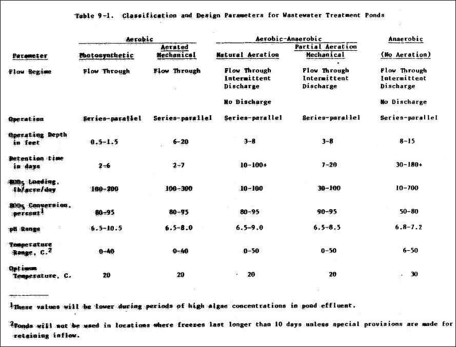
Waste stabilization ponds are classified as aerobic, aerobic-anaerobic (facultative) and anaerobic (Table 9-1).
Aerobic Ponds...
( 1 ) Photosynthetic wastewater treatment ponds : Oxygen to satisfy the requirements of microorganisms in removing
BOD from the wastewater is produced by photosynthesis, utilizing predominately algae, carbon dioxide, and sunlight. The
ponds are 6 to 18 inches deep and most oxygen requirements are met by the algae, with some oxygen provided at the gas-liquid interface . BOD of the pond effluent may be higher than that of the influent because algae are present . To achieve the desired level of BOD reduction in such case, it is necessary to remove the algae from the pond effluent . A major disadvantage is the growth of noxious plants that can accumulate floatable debris which can become septic, create odors,
and allow propagation of mosquitos .
( 2 ) Mechanically aerated wastewater treatment pond : These are completely mixed wastewater treatment ponds
utilizing surface-type aerators, either submerged propeller or turbine-type aerators . The principal source of oxygen is furnished by mechanical aeration rather than by photosynthesis . The solids carry-over from the aeration pond must be
removed by a clarification process following treatment in the aeration pond . The concentration of suspended solids in the effluent is approximately equal to that in the pond .
Aerobic - Anaerobic Ponds ( Facultative )...
( 1 ) Natural aeration mode : These are partially mixed wastewater treatment ponds utilizing the natural ambient environment to provide aeration for the wastewater treatment pond . They are divided by loading and stratification into distinct surface and bottom zones, utilizing aerobic and anaerobic degradation, respectively . Oxygen for aerobic stabilization in the surface layer is provided by photosynthesis and surface reaeration . These are by far the most
widely used ponds for sewage treatment . They are operated as flow-through, intermittent discharge or as complete retention of 10 days to 1 year or more . They may be operated as series or parallel ponds, with or without recirculation . With an influent containing 200 mg/1 suspended solids, the effluent can range up to 400 mg/l because of algae carryover .
( 2 ) Mechanical mode partial aeration : These are partially mixed wastewater treatment ponds, utilizing surface or submerged propeller or turbine aerators to provide distribution but not suspension of solids over the pond . The treatment
is similar to the natural aeration mode, but with a greater. part of oxygen provided from aeration.
Anaerobic Ponds...
These wastewater treatment ponds, constructed to depths of 15 feet, employ no aeration . Anaerobic conditions are
maintained- throughout the facility except at the air-liquid interface . The major portion of the BOD is reduced through methane formation ; chemically bound oxygen is the primary oxygen source . Anaerobic ponds are inherently odoriferous .
Design Parameters for Waste Stabilization Ponds...
The design parameters presented in Table 9-1 will be used for the design of aerobic-anaerobic and aerated ponds . The designer may select specific design values as long as they are within the ranges presented in the table . Stabilization ponds, when required to be aerated, will be aerated by mechanical systems . These devices must be designed to provide sufficient oxygen for biological metabolism and adequate mixing .
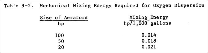
a . Aerated aerobic waste stabilization ponds : The limitation on sizing these ponds will be the ability to maintain aerobic conditions and to increase the effectiveness of the microorganisms by mixing . The aerated aerobic ponds will be designed to keep all active biological solids in suspension and a minimum dissolved oxygen concentration of 2 .0 mg/1 . The power levels required to maintain solids under suspension and to disperse oxygen uniformly throughout the basin are 0.02 to 0.03 hp / 1,000 gallons and 0.006 to 0.015 hp / 1,000 gallons, respectively . A mixing velocity (average velocity of any given particle in the pond) greater than 1 .0 fps should be maintained in the basin to prevent solids deposition . Mixing energy input varies with the size of the aeration unit . The values in Table 9-2 will provide sufficient mixing energy to disperse oxygen uniformly throughout the basin.
Mechanical aerators can be designed to provide either complete mixing of solids including oxygen dispersion, or just to provide uniformly dispersed oxygen . In the latter case, solids deposition will occur in the basin .
b . Aerated aerobic-anaerobic waste stabilization ponds : These ponds will be designed to provide enough oxygen and mixing to maintain an aerobic surface layer throughout the pond . This can be accomplished by using shallow aerators or by maximizing the effect of the wind .
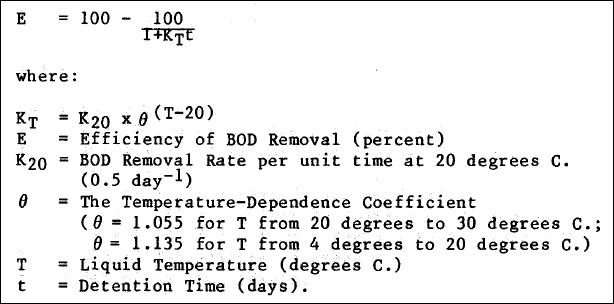
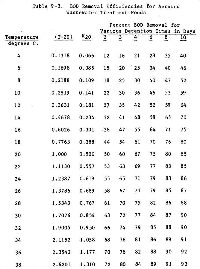
c . BOD removal efficiency : BOD removal efficiency in an aerated pond is a function of temperature and detention
time in the basin . Table 9-3 lists the calculated efficiencies for combinations of different temperatures and detention times . The calculations in Table 9-3 are based on the following equation :
d . Oxygen requirements : Oxygen required in an aeration pond is transferred into the liquid by the mechanical aerators . Surface ventilation and algae may provide, additional amounts of oxygen, but generally are not considered significant . Oxygen requirements for an aerated basin are defined as for activated sludge systems.
e . Horsepower requirement : The horsepower required will be calculated as for activated sludge systems.
f . Further treatment : Aerated pond effluent may be further treated in a "polishing" pond designed for 1 day or
less retention for settling solids, or for longer retention time to provide for additional biological treatment.
g . Pond operation : Ponds, can be designed to operate in series or parallel. Provisions for recirculation will be provided when more than one pond is used .
Pond Facility Requirements...
a . Inlet : Inlet into the pond will be by a single inlet pipe, with discharge into a circular, deeper, sludge
storage zone below the bottom of the normal pond . Discharge will be onto a concrete splash pad or diffusion block . The sludge storage section should have a maximum diameter of 200 feet, but not less than 50 feet, with, a center depth not less than 1 .0 foot, below the normal bottom elevation, with inlet pipe discharge at the center of the sludge storage section .
The discharge will be located near the leeward side of the pond or at right angle to the prevailing winds near the end most remote from the outlet structure . The inlet pipe from point of discharge to the outer berm of the dike will be on a level grade at a depth sufficient to provide adequate freeze protection when the pond is at minimum operating level at maximum freeze depth . A standard manhole will be placed in the outer berm of the pond dike on the inlet pipe . The manhole will
be utilized for rodding the inlet pipe or surge pumping through the discharge to maintain a clean open inlet . The splash block, or discharge diffusion block, will be so designed that scouring of the bottom will not occur with the above
operations .
b . Outlet structures : Outlet structures will permit lowering the water level at a rate of not less , than 1 .0
foot per week while the pond is receiving its normal flow . Provisions will be made for complete drainage of the pond . Outlet structures will be located on the windward side of the dike at a point most remote from the inlet, will be large enough to permit easy access for normal maintenance, and will provide complete draining of the pond . The outlet from each cell should have the capacity to change the depth from maximum to minimum operating depth in 6-inch increments to give operational flexibility as well as a drain for the entire pond . The structure will be designed to minimize velocities at
any point of withdrawal . In small ponds with normal discharge of 50,000 gpd or less, a large pipe with adjustable sections is adequate . Outlet velocity across the pipe entrance must be kept under 0 .5 fps . The provision will be met with an adjustable weir in ponds with discharge in excess of 50,000 gpd . There will be three sets of baffles concentrically around the outlet structure(s) . The first baffle will extend 3 to 5 feet around the outlet structure, with the baffle extending at least 6 inches to 1 foot above the highest water level and down to within 1 foot of the bottom of the pond . The second baffle is set in the bottom of the pond and extends to within 6 inches of the lowest anticipated operating level . The
third baffle is the same as the first . When design includes siphoning, outlet line(s) will be vented .
c . Dikes : Dikes will have a minimum top width 10 feet, a minimum freeboard at 2 feet above high water level, and side slopes of a minimum 3 horizontal to 1 vertical for inside and outside slopes . Determination of slope will based on
natural angle of repose of the soil, length of open water, slope protection provided, and soil characteristisc. Dikes will
be compacted to 90 percent of maximum density at optimum moisture content and sealed against seepage. An excavated drain
will be provided at the toe of the exterior slope to convey seepage water, over-topping loss, or spillage due to dike
failure to the receiving watercourse for the waste stabilization pond discharge . Protection from wind and water erosion
will be provided as needed .
d . Bottom : The bottom will be as level as practicable with variations not exceeding 6 inches from the designed bottom elevation . This does not apply to the dished area around the inlet, covered by paragraph 9-3 .a . The bottom will
be cleared, grubbed, and sealed to prevent loss of liquid through excess seepage . If ground water protection is a requirement or desirable, then a liner would be necessary depending on soil permeability . If the soil permeability is
10 - 7 cm / sec or better, a liner would not be required . For lesser permeabilities, a water barrier of some
kind should be provided . Some acceptable lining materials are various synthetics, bentonite, clay, or pavement materials such as concrete or asphalt .
e . Surface runoff control : Surface runoff will be excluded, from wastewater treatment ponds . Intercepting drains, diversion ditches, and / or dikes will be constructed as required to comply with this requirement . When surface drainage must be rerouted to meet the requirement, rerouted drainage will be routed to the original drainage course to the maximum extent possible .
f . Fencing and access : The entire wastewater treatment ponds area will be provided with a locked security fence
that will have a double wide gate for vehicular access . A gravel road not less than 10 feet wide will be provided through this gate and around the new dike.
g . Flow operation modes : In no case will a raw wastewater treatment pond have less than two cells . Operation will normally be in series, with piping flexibility permitting parallel or series operation, recirculation if desired, and isolation and removal from service of any unit without interference in operation of any other unit . The maximum design BOD loading rate to each pond cannot be exceeded for any mode of operation .