Trickling Filter - 4...
General Considerations...
Trickling filter plants have been justified by their low initial cost, low operating and maintenance costs, and simplicity
of operation. Although the effluent from trickling filter plants of earlier design was of poorer quality than that from activated sludge plants, the performance of trickling filters designed more recently is comparable to that of activated sludge plants. Both processes offer certain advantages, with trickling filters providing good performance with minimal operator care and few, if any, energy requirements. Trickling filters are classified as low-rate or high-rate, and
according to the organic loading applied. Another classification is shallow and deep filters ; usually, filters less than 7 feet deep are considered to be shallow filters ; those with a greater depth are considered to be deep trickling filters. Filters are also classified according to the type of media utilized, i .e ., rock or synthetic media.
Design Basis and Criteria...
The designer will provide preliminary and primary treatment ahead of the filters, and circular or rectangular settling
tanks with mechanical sludge removal equipment following the filters. Design criteria for settling tanks are in chapter 8. Table 10-1 gives design data for the trickling filter process. The designer normally will use the average of the hydraulic
or organic loading ranges presented in Table 10-1 for the design of each filter class, unless special conditions warrant
the use of values other than the average.
( a ) Filter Depth : Stone media trickling filters will be designed
with depths of 5 to 7 feet for low-rate and depths of 3 to 6 feet for high-rate applications. Synthetic media manufacturers recommend depths of 10 to 40 feet for columnar or stacked module media. Randomly placed polypropylene media filters are designed within the depth ranges of the low-rate filters. The deeper trickling filters can improve nitrification potential and can be used as the second stage in two-stage biological system designs for nitrification.
( b ) Recirculation : This is an accepted method of increasing the BOD removal efficiency of high-rate trickling filter processes. Figure 10-1 shows acceptable recirculation systems for single-stage and two-stage trickling filters treating domestic wastewater. Table 10-2 lists recommended recirculation rates for high-rate filters. Whether to use recirculation, and the amount to be recycled when used, are matters of economics which may involve either first cost or annual costs of various designs providing equal treatment. Unless other conditions control, recirculation should provide continuous dosing at a minimum surface application rate of 10 mgad. In flow diagrams B, C, and D (Figure 10-1) fluctuations in the organic loading applied to the filter are dampened. Filter sloughings are recycled to the filter in flow diagram A, but little, if any, dampening of variations in organic loading is provided. Flow diagram E may include a low-rate filter
for the second-stage unit. Intermediate settling tanks will always be provided between first and second stage filters. Flow diagrams G and H attempt to improve treatment by developing greater biological activity on the second stage filter, but are not acceptable for Army installations because there are no intermediate clarifiers. Flow diagrams E, F, G, and H require inclusion of the recirculated flow in the forward flow used for design of any tanks through which it passes.
Table 10-1. Design data, and information for trickling filter processes...
Figure 10-1. Common flow diagrams for single and two-stage high-rate trickling filters...
Table 10-2. Design recirculation rates for high-rate filters...

( c ) Hydraulic and Organic Loadings : Loading rate is the key design factor, whether the surface application
is continuous, intermittent, a constant rate, or a varying rate. The BOD removal efficiencies obtainable for specific wastewater organic and hydraulic loading from trickling filter installations can be compared when the loadings are
within the ranges presented in Table 10-1 and the trickling filter performance formula described in paragraph 10-2.f.(1)
is utilized.
( d ) Ventilation : Ventilation provides aerobic conditions required for effective treatment. Design for ventilation will provide the following :
( 1 ) Underdrains and collecting channels designed to flow half full at maximum design flow.
( 2 ) Ventilating manholes with open grate covers installed at both ends of the central collecting channel.
( 3 ) Branch collecting channels with ventilating manholes or vent stacks installed at the filter periphery for
units over 50 feet in diameter.
( 4 ) Open area of slots in the top of the underdrain blocks not less than 15 percent of the area of the filter.
( 5 ) Peripheral duct (or channel) interconnecting vent stacks and collecting channels.
( 6 ) One square foot of gross area of open grating in the ventilating manholes and vent stacks for each 250 square feet
of filter surface.
( 7 ) When the trickling filter is constructed with top of media or distributor arms at or near grade, with underdrain
system more than 3 feet below grade, or when normal climatic conditions do not include adequate air movement, ventilation shafts will be provided.
( e ) Temperature : The performance of trickling filters will be affected by temperature changes in the
wastewater and filter films. Filter efficiency changes attributed to temperature variations are expressed by the
following formula :
The temperature formula will be used to correct the filter performance predicted by the NRC design formula. In areas that experience prolonged cold and/or icing, wind breaks or dome covers for trickling filters to prevent freezing problems will
be considered.
( f ) Plant Efficiencies : Performance efficiencies, given as BOD removal, of single-stage and two-stage filters,
are to be estimated using formulas in the following section :
( 1 ) National Research Council (NRC) formulas : The NRC formulas will be used to design all stone-media trickling filters for Army installations. NRC developed the following formulas for predicting the stone-media trickling filter performance at 20 degrees C.
( 2 ) Other design formula : Although the NRC formula is required for design of stone-media filters, the following formula
is appropriate for stacked synthetic media filters :
Nitrification in Trickling Filters...
The development and maintenance of nitrifying organisms in trickling filter systems depend mainly on the organic loading
and wastewater temperature. Generally, nitrification occurs best at low BOD loadings (less than 5 pounds BOD/day.1,000
cubic feet) and high wastewater temperature (20 degrees C or higher). The degree of nitrification in trickling filters
improves as the volumetric BOD loading is reduced. Depending on effluent requirements, in colder climates existing
trickling filter plants will be modified to achieve a high degree of nitrification year-round, or only during the warmer months of the year. Year-round nitrification facilities will be designed. For the lowest daily average wastewater temperatures experienced in the winter months. In this instance, the required filter volume will be greater than that required for seasonal nitrification and will require at least two-stage treatment. Trickling filters intended to provide
80 to 90 percent nitrification will be designed at a hydraulic loading of 50 gpd/square foot and an organic loading of 4 pounds BOD/day.1,000 cubic feet.
Hydraulic Components...
( a ) Influent Distributors : Rotary reaction distributors consisting of two or more horizontal pipes supported by
a central column are available for dosing filter beds ranging from 20 to more than 200 feet in diameter. Distributors will
be sealed by pressurized oil, neoprene gaskets, or air-gap "non-seal" methods. Hydraulic head requirements for distributors vary approximately as the square of the influent flow, with the hydraulic gradient usually 12 to 24 inches above the center
line of the distributor arms at minimum flow. Distributor design must provide : ( 1 ) a means for correcting alinement,
( 2 ) adequate structural strength, ( 3 ) adequate pipe size to prevent velocities In excess of 4 fps at maximum flow,
( 4 ) bearings, ( 5 ) drains for dewatering the Inflow column, and ( 6 ) pipe and openings at the end of each arm for ease
of removing ice buildups during winter operation. A minimum clearance of 6 inches between media and distributor arms will
be provided. Motor-driven rotary distributors will be used only if the minimal hydraulic head to drive the distributor Is
not available. Positive drive will be provided by a totally enclosed electric motor and gear arrangement.
( b ) Dosing Siphons : Wastewater may be applied to the filters by pumps, by gravity discharge from preceding treatment units when suitable flow characteristics have been developed, and by siphons. Frequently during the day the flow will be be less than the minimum set by the distributor. If this is the case, a dosing tank and alternating siphons will be required for each filter unit. Each siphon will have a dosing tank with a volumetric capacity equal to the average flow rate for a 4-minute period so that dosing is nearly continuous.
( c ) Head Loss Computations : The net available head on the horizontal center line of the distributor arms will be calculated by deducting the following applicable losses from the available static head :
- Entrance loss from the primary settling tank.
- When using - dosing siphons : the drop in tank level dosing as distributor pipes are filled, the friction losses in the siphon itself, and the velocity head imparted from the siphons.
- Friction losses in piping and fittings.
- Loss through distributor column rise and center port.
- Friction loss in distributor arms and velocity head of discharge through nozzles necessary to start reactor-type rotary
distributors in motion . The hydraulic head requirements of distributors are specified by the manufacturers. The major
head loss is the elevation difference between the distributor arms and the lowest water surface in the main underdrain channel. Approximately 8 feet of head is lost in a 6-foot deep filter.
( d ) Other Filter Components : Table 10-3 gives a list of other components normally associated with trickling
filters and for which design requirements are specified. Trickling filter design must include provisions for flooding the filter and the filter walls, and appurtenances must be able to structurally withstand the resulting hydrostatic pressure forces when the filter is flooded. In northern regions that are subject to extreme and/or prolonged freezing conditions, including high wind chill factors, design considerations must be given to providing filter dome covers or wind breaks.
Figure 10-2 is a sectional view of a trickling filter.
Table 10-3.Miscellaneous trickling filter component design criteria...
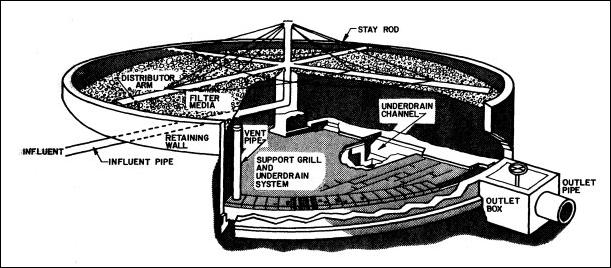
Figure 10-2.Trickling filter components...