Trickling Filter - 5...
Description...
Trickling filters (TFs) are used to remove organic matter from wastewater. The TF is an aerobic treatment system that utilizes microorganisms attached to a medium to remove organic matter from wastewater. This type of system is common
to a number of technologies such as rotating biological contactors and packed bed reactors (biotowers). These systems are known as attached-growth processes. In contrast, systems in which microorganisms are sustained in a liquid are known as suspended-growth processes.
Applicability...
TFs enable organic material in the wastewater to be adsorbed by a population of microorganisms (aerobic, anaerobic, and facultative bacteria; fungi; algae; and protozoa) attached to the medium as a biological film or slime layer (approximately 0.1 to 0.2 mm thick). As the wastewater flows over the medium, microorganisms already in the water gradually attach themselves to the rock, slag, or plastic surface and form a film. The organic material is then degraded by the aerobic
microorganisms in the outer part of the slime layer.
As the layer thickens through microbial growth, oxygen cannot penetrate the medium face, and anaerobic organisms develop. As the biological film continues to grow, the microorganisms near the surface lose their ability to cling to the medium, and a portion of the slime layer falls off the filter. This process is known as sloughing. The sloughed solids are picked up by
the underdrain system and transported to a clarifier for removal from the wastewater.
Advantages and Disadvantages...
Some advantages and disadvantages of TFs are listed below.
Advantages...
- Simple, reliable, biological process.
- Suitable in areas where large tracts of land are not available for land intensive treatment systems.
- May qualify for equivalent secondary discharge standards.
- Effective in treating high concentrations of organics depending on the type of medium used.
- Appropriate for small- to medium-sized communities.
- Rapidly reduce soluble BOD5 in applied wastewater.
- Efficient nitrification units.
- Durable process elements.
- Low power requirements.
- Moderate level of skill and technical expertise needed to manage and operate the system.
Disadvantages...
- Additional treatment may be needed to meet more stringent discharge standards.
- Possible accumulation of excess biomass that cannot retain an aerobic condition and can impair TF performance (maximum biomass thickness is controlled by hydraulic dosage rate, type of media, type of organic matter, temperature and nature of the biological growth).
- Requires regular operator attention.
- Incidence of clogging is relatively high.
- Requires low loadings depending on the medium.
- Flexibility and control are limited in comparison with activated-sludge processes.
- Vector and odor problems.
- Snail problems.
Design Criteria...
A TF consists of permeable medium made of a bed of rock, slag, or plastic over which wastewater is distributed to trickle through, as shown in Figure 1. Rock or slag beds can be up to 60.96 meters (200 feet) in diameter and 0.9-2.4 meters (3 to 8 feet) deep with rock size varying from 2.5-10.2 cm (1 to 4 inches). Most rock media provide approximately 149
m2/m3 (15 sq ft/cu ft) of surface area and less than 40 percent void space. Packed plastic filters
(bio-towers), on the other hand, are smaller in diameter (6 to 12 meters (20 to 40 feet)) and range in depth from 4.3 to
12.2 meters (14 to 40 feet). These filters look more like towers, with the media in various configurations (e.g., vertical flow, cross flow, or various random packings). Research has shown that cross-flow media may offer better flow distribution than other media, especially at low organic loads. When comparing vertical media with the 60 degree cross-flow media, the vertical media provide a nearly equal distribution of wastewater minimizing potential plugging at higher organic loads
better than cross flow media. The plastic medium also required additional provisions, including ultraviolet protective additives on the top layer of the plastic medium filter, and increased plastic wall thickness for medium packs that are
installed in the lower section of the filter where loads increase.
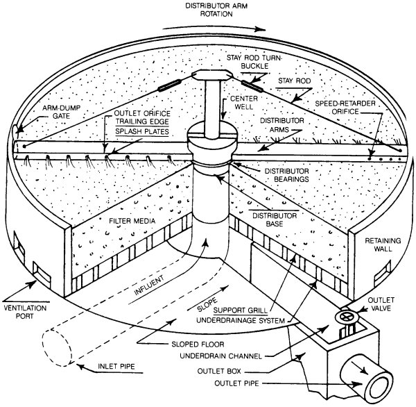 Figure 1. Typical trickling filter...
The design of a TF system for wastewater also includes a distribution system. Rotary hydraulic distribution is usually standard for this process, but fixed nozzle distributors are also being used in square or rectangular reactors. Overall, fixed nozzle distributors are being limited to small facilities and package plants. Recently some distributors have been equipped with motorized units to control their speed. Distributors can be set up to be mechanically driven at all times or during stalled conditions.
In addition, a TF has an underdrain system that collects the filtrate and solids, and also serves as a source of air for
the microorganisms on the filter. The treated wastewater and solids are piped to a settling tank where the solids are separated. Usually, part of the liquid from the settling chamber is recirculated to improve wetting and flushing of the filter medium, optimizing the process and increasing the removal rate.
It is essential that sufficient air be available for the successful operation of the TF. It has been found that to supply
air to the system, natural draft and wind forces are usually sufficient if large enough ventilation ports are provided at
the bottom of the filter and the medium has enough void area. The following four basic categories of filter design are based on the organic loading of the trickling filter.
Low - Rate Filters...
Low-rate filters are commonly used for loadings of less than 40 kilograms five day biochemical oxygen demand (BOD5)/100 meters cubed per day (25 lb BOD5/1000cu ft/day). These systems have fewer problems than other filters with regards to filter flies, odors, and medium plugging because of the lower loading rate. Low-rate filters with a rock medium range in depth from 0.9 to 2.4 meters (3-8 ft.). Most low-rate filters are circular with rotary
distributors, but some filters currently in use are rectangular. Both of these configurations are equipped with dosing syphons or periodic pumps to provide a high wetting rate for short intervals between rest periods. A minimum wetting rate
of 0.4 liters per square meter-second (0.7 gal/sq ft/min) is maintained to prevent the high rate plastic filter medium from drying out. With a rock medium, the filters tend not to be hydraulically limited and have application limits ranging from
0.01 to 0.04 liters per square meter-second (0.02 to 0.06 gal/sq ft/min).
The sloughed solids from a low-rate filter are generally well-digested and as a result these filters yield less solids than higher rate filters. Secondary quality effluent is readily achievable if the low-rate trickling filter design incorporates filter media with bioflocculation capabilities or good secondary clarification.
Intermediate - Rate Filters...
Intermediate rate filters can be loaded up to 64 kg BOD5/100 m3-d (40 lb BOD5/1,000 cu ft/day). In order to ensure good distribution and thorough blending of the filter and secondary effluent, the system should recirculate the trickling filter effluent. The biological solids that slough from an intermediate trickling filter are not
as well digested as those using a low-rate filter.
High - Rate Filters...
High-rate filters are generally loaded at the maximum organic loading capabilities of the filter and receive total BOD5 loading ranging from 64 to 160 kg BOD5/100 m3-d (40 to 100 lb. BOD5/1,000
cu ft/day). Achieving a secondary quality effluent is less likely for a high-rate filter without a secondstage process. As
a result, high-rate filters are often used with combined processes.
Roughing Filters...
Roughing filters are designed to allow a significant amount of soluble BOD to bleed through the trickling filter. Filters of this type generally have a design load ranging from 160-480 kg BOD5/100 m3-d (100 to 300 lb. BOD5/1,000 cu ft/day).
Performance...
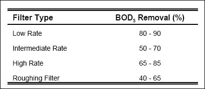
Recent efforts have been made to combine fixedfilm reactors with suspended growth processes to efficiently remove organic materials from wastewater. For example, the combination of a trickling filter with an activated-sludge process has
allowed for the elimination of shock loads to the more sensitive activated sludge while providing a highly polished effluent that could not be achieved by a trickling filter alone. Table 1 shows the BOD5 removal rates for the four filter types discussed.
Although the TF process is generally reliable, there is still potential for operational problems. Some of the common
problems are attributed to increased growth of biofilm, improper design, changing wastewater characteristics, or equipment failure. Some common problems with TF function are discussed in the Operation and Maintenance section.
Table 1. BOD5 removal rates for various filter types...
Operation and Maintenance...
Disagreeable Odors from Filter...
Potential Cause : Excessive organic load causing anaerobic decomposition in filter.
Remedy : Reduce loading; increase BOD removal in primary settling tanks; enhance aerobic conditions in treatment
units by adding chemical oxidants, preaerating, recycling plant effluent, or increasing air to aerated grit chambers; scrub off gases; use plastic media instead of rock.
Potential Cause : Inadequate ventilation.
Remedy : Increase hydraulic loading to wash out excess biological growth; remove debris from filter effluent
channels, underdrains, and the top of filter media; unclog vent pipes; reduce hydraulic loading if underdrains are flooded; install fans to induce draft through filter; check for filter plugging resulting from breakdown of the medium.
Ponding on Filter Media...
Potential Cause : Excessive biological growth or foreign matter in or on the filter.
Remedy : Reduce organic loading; increase hydraulic loading to increase sloughing; use high-pressure stream of water to flush filter surface; maintain 1 to 2 mg/L residual chlorine on the filter for several hours; flood filter for 24 hours; shut down filter to dry out media; replace media if necessary; remove debris.
Filter Flies (Psychoda)...
Potential Cause : Inadequate filter media moisture.
Remedy : Increase hydraulic loading; unplug spray orifices or nozzles; use orifice opening at end of rotating distributor arms to spray filter walls; flood filter for several hours each week during fly season; maintain 1-2 mg/L residual chlorine on the filter for several hours.
Potential Cause : Poor housekeeping.
Remedy : Mow area surrounding filter and remove weeds and shrubs.
Icing...
Potential Cause : Low temperature of wastewater.
Remedy : Decrease recirculation; use high-pressure stream of water to remove ice from orifices, nozzles, and distributor arms; reduce number of filters in service as long as effluent limits can still be met; reduce retention time in pretreatment and primary treatment units; construct windbreak or covers.
Rotating Distributor Slows Down or Stops...
Potential Cause : Insufficient flow to turn distributor.
Remedy : Increase hydraulic loading; close reversing jets.
Potential Cause : Clogged arms or orifices.
Remedy : Flush out arms by opening end plates; remove solids from influent wastewater; flush out orifices.
Potential Cause : Clogged distributor arm vent pipe.
Remedy : Remove material from vent pipe by rodding or flushing; remove solids from influent wastewater.
Potential Cause : Distributor arms not level.
Remedy : Adjust guy wires at tie rods.
Potential Cause : Distributor rods hitting media.
Remedy : Level media; remove some media.
Rotary Distributors...
Rotary distributors are very reliable and easy to maintain. A clearance of 15.2-22.9 centimeters (6-9 inches) is needed between the bottom of the distributor arm and the top of the medium bed to allow the wastewater from the nozzles to spread out and cover the bed uniformly. This also helps prevent ice from accumulating during freezing weather. Care should be
taken to prevent leaks. Follow the manufacturer's operation and maintenance (O&M) instructions on pumps, bearings, and motors. All equipment must be tested and calibrated as recommended by the equipment manufacturer. A routine O&M schedule should be developed and followed for any TF system. It is critical that a TF system be pilot tested prior to installation
to ensure that it will meet effluent discharge permit requirements for that particular site.
Disagreeable Odors from Filter...
- Excessive organic load causing anaerobic decomposition in filter : Reduce loading; increase BOD removal in primary
settling tanks; enhance aerobic conditions in treatment units by adding chemical oxidants, preaerating, recycling plant effluent, or increasing air to aerated grit chambers; scrub off-gases; use plastic media instead of rock.
- Inadequate ventilation : Increase hydraulic loading to wash out excess biological growth; remove debris from filter effluent channels, underdrains, and the top of filter media; unclog vent pipes; reduce hydraulic loading if underdrains are flooded; install fans to induce draft through filter; check for filter plugging resulting from breakdown of media.
Ponding on Filter Media...
- Excessive biological growth : Reduce organic loading; increase hydraulic loading to increase sloughing; use high-pressure stream of water to flush filter surface (recycled water); maintain 1 to 2 mg/L residual chlorine on the filter for several hours; flood filter for 24 hours; shut down filter to dry out media; replace media if necessary; remove debris.
Filter Flies (Psychoda)...
- Inadequate moisture on filter media : Increase hydraulic loading; unplug spray orifices or nozzles; use orifice opening
at end of rotating distributor arms to spray filter walls; flood filter for several hours each week during fly season; maintain 1 to 2 mg/L residual chlorine on the filter for several hours.
- Poor housekeeping : Mow area surrounding filter and remove weeds and shrubs.
Icing...
- Low temperature of wastewater : Decrease recirculation; use high-pressure stream of water to remove ice from orifices, nozzles, and distributor arms; reduce number of filters in service as long as effluent limits can still be met; reduce retention time in pretreatment and primary treatment units; construct windbreak or covers.
Rotating Distributor Slows Down or Stops...
- Insufficient flow to turn distributor : Increase hydraulic loading; close reversing jets.
- Clogged arms or orifices : Flush out arms by opening end plates; remove solids from influent wastewater; flush out orifices.
- Clogged distributor arm vent pipe : Remove material from vent pipe by rodding or flushing; remove solids from influent
wastewater.
- Distributor arms not level : Adjust guy wires at tie rods.
- Distributor rods hitting media : Level media; remove some media.
Rotary distributors are very reliable and easy to maintain. A clearance of 15 to 23 cm (6 to 9 inches) is needed between
the bottom of the distributor arm and the top of the media bed to allow the wastewater from the nozzles to spread out and cover the bed uniformly. This also prevents ice from accumulating during freezing weather. Care should be taken to prevent leaks. Follow the manufacturer's operation and maintenance (O&M) instructions on pumps, bearings, and motors. All
equipment must be tested and calibrated as recommended by the equipment manufacturer. A routine O&M schedule should be developed and followed for any TF system. It is critical that a TF system be pilot tested prior to installation to ensure
that it will meet effluent discharge permit requirements for that particular site.
Cost...
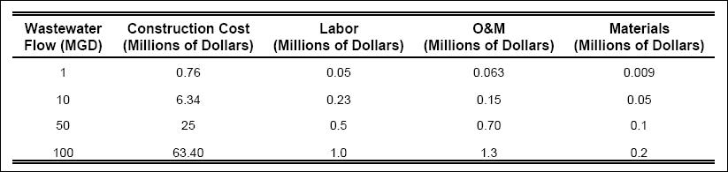
The cost for a TF system are summarized in Table 2. These costs include construction, labor, total O&M, and materials
needed. Since every TF system is unique to its site, the overall cost will be site specific.
Table 2. Cost Summary for a Trickling Filter...