Sedimentaton...

Type Description Examples
Discrete
(Type - I)
Individual settling, low solids concentration Grit, sand
Flocculant
(Type - II)
Dilute suspension, particles flocculate, mass and settling rate increase with depth Primary and upper secondary settlers
Hindered
(Type - III)
Intermediate concentration, mass settles as a unit, interface at top Secondary clarifiers
Compression
(Type - IV)
High concentration, structure formed, compression causes settling Sludge

Discrete (Type - I) : Newton / Stokes Analysis...

Set gravitational forces = frictional resistance. From Newton's second law :

Where ; m : mass, dV / dt : settling velocity, Fg : weight, Fb : bouyancy and Fd : drag.

Gravitational force = Fg - Fb = (rs - r) (g) (Vp)

Where ; r : density of fluid, r s : particle density, g : acceleration due to gravity and Vp : volume of particle.

Drag force ;

Where ; CD : drag coefficient, Ap : particle area and Vs : particle velocity.


We can therefore rewrite the equation as :

After an initial transient period the system will reach steady-state so that

and

Solving for Vs ;

The Stokes Approximation...

- Assume every particle is a sphere, so that

- For Reynolds (Re) numbers < 0.1 ;

Where ; µ : fluid viscosity and dp : particle diameter.

All particles with velocities Vsi> Vsc (critical settling velocity) will settle. Particles with settling velocities < Vsc will be removed in proportion to the ratio Vsi / Vsc. The fraction removed can be calculated from ;

Some of the real-world particle characteristics which do not entirely conform to the assumptions used in this analysis include ; (1) non-spherical particles, (2) variable particle density, (3) uneven flow through the tank, (4) size fractionation and (5) particle contact, with large particles interferring with smaller ones.

Note : The Reynolds number should be less than 0.1 to use the Stokes approximation. A comparison between the Stokes approximation and the complete iterative solution for spherical particles is provide in the figures below.


Design Flowrate...

Q = (A) (Vsc)

Where ; Q : flowrate (m3 / s), A : area of basin (= width x length, m2) and Vsc : critical settling velocity (the velocity of particles which just settle in the basin (m / s).

Design Process Based on Discrete Settling...

To be conservative, size the settling basin for smallest particle to be removed : Q = (A) (Vc); where Q : flowrate and A = surface area of basin. Note that size is independent of the depth of the reactor, so stacked shallow systems are most efficient (but plate and tube settlers often clog). Flocculant Settling (Type - II) : need to determine settling characteristics in a settling column with height = height of tank. Hindered (Type - III) and Compression (Type - IV) settling : need to consider areas required for clarification, thickening, and sludge withdrawal. Thickening requirements usually predominate, and graphical techniques can be used to estimate the area.

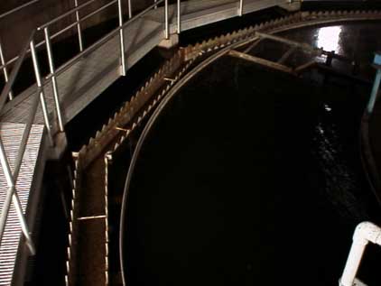
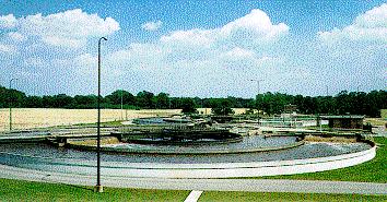
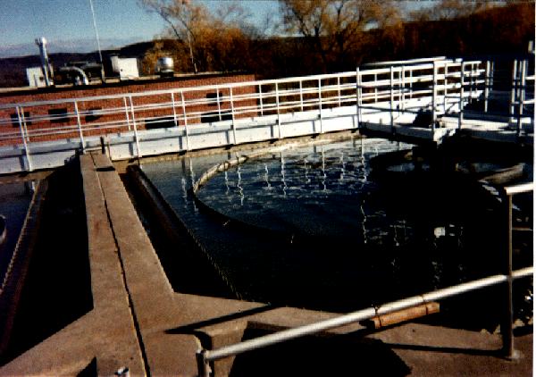
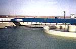
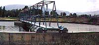
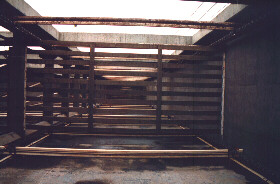
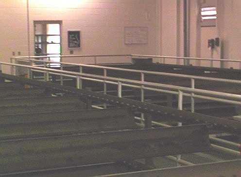
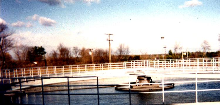
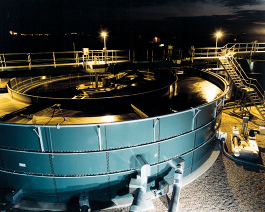
"Longidutal Section of a Circular Sedimentation Tank"...

Settling Basin Design...

For any clay-sized or larger particle in suspension in a fluid, the settling rate is a function of the gravitational force (downward) and the frictional resistance (opposite). Because the mass of a particle increases with the cube of the radius, but drag surface area only increases with the square of the radius, larger particles settle more quickly than small particles. Very small particles (such as the colloidal particles in milk), can be kept in solution indefinately by static charges and brownian motion, so settling basins are ineffective at removing these particles. The essence of the design process is to determine a specific residence time, dependent on a particle size goal. The sediment removal will include all particles with a velocity > Vc, plus that fraction of the slower (smaller) particles that enter low enough in the column to also settle to the sludge layer before passing out of the basin.

In order to theoretically calculate the critical velocity of the smallest consistently removed particle using Stoke's law (for small Reynolds numbers), we must know the particle density, fluid viscosity, and the drag coefficient. In practice, a settling column experiment is often used to determine the settling velocity of the different fractions of a suspension, along with the mass of sediment in each fraction.


For a given Vc, the fraction removed ;


With data on Vp for a range of fractions dx, we can rewrite the integral as a sum ;

and thus integrate manually.

The settling basin is sized for smallest particle to be removed, using the following equation ; Q = (A) (Vc). Where ; Q : flowrate, A : surface area of basin, and Vc : is the terminal settling velocity of the smallest particle for which settling is desired. Note that the size of the basin required is a function of area but not depth, so shallow systems are most efficient (and are therefore sometime stacked in municipal and industrial applications). In practice, we must adjust the resulting Q / A ( = Vc) for the effects of inlet and outlet turbulence, non-uniform fluid flow, and sludge storage. Most settling basins are designed to achieve a 5 to 10 minute residence time, which should settle 50 to 75% of the solids from open feedlot runoff. At 6 minutes residence time, the nominal size of the smallest consistently separated particule is 35 microns, with a calculated terminal velocity Vc of 0.84 cm / s.


Design Example - 1...

Given : (1) two rectangular primary clarifiers ; (2) dimensions : 40 ft x 12 ft x 7 ft deep ; (3) effluent weir length = 45 ft ; (4) Q = 387,000 gpd.
Required : (1) overflow rate ; (2) weir loading ; (3) detention time ; (4) estimated BOD removal.

Solution...

Flow per clarifier : 387,000 gpd / 2 = 193,500 gpd
Overflow rate : 193,500 gpd / [ (40 ft) (12 ft) ] = 403 gpd / ft2
Weir loading : 193,500 gpd / 45 ft = 4,300 gpd / ft
Detention time : [ (40 ft) (12 ft) (7 ft) ] / 193,500 gpd = 3.1 hr
Estimated BOD removal : 35 % (typical range is 30 % - 40 %)

Design Example - 2...

Brief Info...

• Purpose – to remove settable organic solids and to reduce the solids load on the biological treatment unit
• Primary sedimentation or clarification is achieved in large basins under relatively quiescent conditions

Two types of design available : Horizontal flow and circular.


Design Criteria :

• Overflow rate ( gpm/ft2 or m3/m2/day )
• Weir overflow rate ( gpm/ft or m3/m.day )
• Detention time ( hours )
• Solids loading rate ( lbs/ft2/day or kg/m2.day )
(More important for secondary sedimentation tanks)


Expected BOD and suspended solids removal between 30 – 40 % and 50 – 70 %, respectively.

Design a sedimentation tank for a municipal wastewater with an average flow of 5.000 m3/day and a peak hourly flow = 12,500 m3/day.
Assume 60 % SS removal, overflow rate = 35 m3/m2/day.

1. Required surface area, A = 5,000 / 35 = 143 m2
2. Circular tank diameter, d = ( 4 x 143 / 3.142 )1 / 2 = 13.5 m
(Have to select size appropriate for circular scraper)
3. Assume 15 m diameter ( To fit a 15 m diameter scraper )
Surface area needed, AN = ( 3.142 x 152 ) / 4 = 176.7 m2
4. Assume side wall depth = 3 m
Volume of tank, V = 176.7 x 3 = 530.1 m3
5. Detention time, t = 530.1 / 5,000 = 0.106 days = 2.54 hrs (ok)
6. For peak hourly flow requirements, find overflow rate, v = 12,500 / 176.7 = 70.7 m3/m2.day (ok)
7. Check weir overflow rate QW = 12,500 / ( 3.142 x 15 ) = 265 m3/m.day (ok)
8. SS removal at peak flow rate, E = 40 %