Settling Tank...
Tank Types...
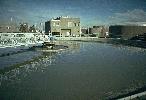
The function of the activated sludge settling tank is to separate the activated sludge solids from the mixed liquor. Solid
separation is the final step in the production of a well - clarified, stable effluent low in BOD and suspended solids and,
as such, represents a critical link in the operation of an activated sludge treatment process. The most commonly used types
of activated sludge settling tanks are either circular or rectangular. Square tanks are used on ocasion, but
are not as effective in retaining separated solids as circular or rectangular tanks. Solids accumulate in the corners of
the square tanks and are frequently swept over the weirs by the agitation of the sludge collectors.
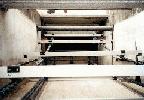
Rectangular Tanks...
Rectangular tanks must be proportioned to achieve proper distribution of incoming flow so that horizontal velocities are not
excessive. It is recommended that the maximum length of rectangular tanks not exceed 10 to 15 times the depth,
but lengths up to 90 m have been used succesfully in large plants. Regardless of tank shape, the sludge collector
should be able to meet the following operational conditions ; (1) the collector should have a high capacity so that when a
high sludge recirculation rate is desired and (2) the mechanism should be sufficiently rugged to be able to transport and
remove the very dense sludges that could accumulate in the settling tank during periods of mechanical breakdown or power
failure.
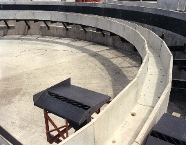
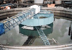
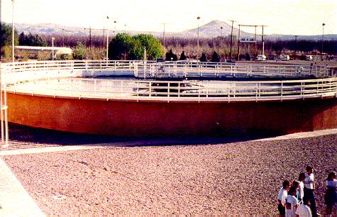
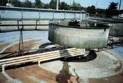
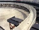
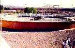
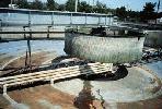
Circular Tanks...
Circular tanks have been constructed with diameters ranging from 3 to 60 m, although the more common range is
from 10 to 40 m. The tank radius should preferably not not exceed 5 times the sidewater depth. Both
the center - feed and the rim - feed clarifiers use a revolving mechanism to transport and remove the sludge from the
bottom of the clarifier.
Schematic Comparison...
Design Criteria...
Secondary clarifiers must be designed for effluent clarification and solids thickening, both of which relate directly to
the surface area. To determine the required surface area, an under - flow concentration is selected and the overflow rate
and limiting solids flux established or assumed for the particular activated sludge under consideration. Batch analysis
can be used to provide overflow rates and thickening characteristics, provided appropriate samples of activated sludge
are available. The single test at the expected concentration Co is sufficient to establish the over -
flow rate. The straight - line portion of the interface vs. time graph establishes the settling velocity of the initial
concentration and thus establishes the overflow rate. Because it is not possible to determine concentration-velocity
relationships in the thickening zone, a series of tests, each at different initial concentrations, is necessary to
establish the solids flux curve. Only the straight-line portion of each curve is used to obtain the velocity v
relating to each concentration X. The resulting solids flux is v.X. It is often necessary to design settling
facilities without the benefit of settling tests. When this situation develops, published values for surface - and
solids - loading rates must be used. Because of the large amount of solids that may be lost in the effluent if
design criteria are exceeded, effluent overflow rates should be based on peak flow conditions. Typical loading criteria
for the design of settling tanks are shown below. The hydraulic retention time of secondary clarifiers must be within the
range of 2 to 4.5 h.
 "Design Criteria"...
Flow Distribution...
Flow imbalance between multiple process units can cause under- or overloading of the individual units and affect overall
system performance. In plants where parallel tanks of the same size are used, flow between the tanks should be equalized.
Most popular method of flow distribution to the secondary sedimentation tanks is distribution well.

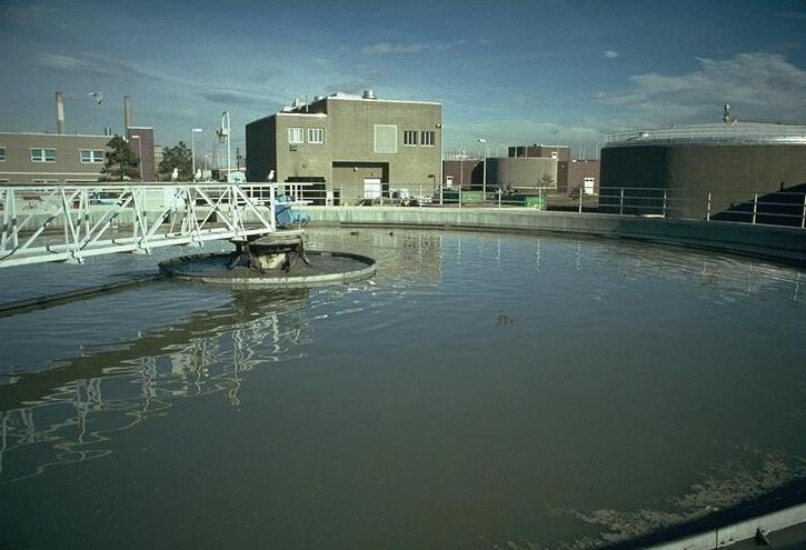
Influent Well...
In circular center - feed tanks, the most common design used, small, solid skirted, cylindrical baffles are provided to
dissipate the influent energy and distribute flow. It has been observed in full - scale studies that a density current
waterfall can be created using skirted baffles resulting in poor vertical flow distribution. Methods to overcome these
problems include the use of a large - center diffusion well or a flocculating - type clarifier. The large - center
diffusion well, with a minimum diameter of 25 % of the tank diameter, provides a greater area for the dissipation
of the influent energy and the distribution of the incoming mixed liquor. The bottom of the feed well should end well
above the sludge - blanket interface to minimize turbulence and resuspension of the solids. In rectangular tanks, inlet
ports or baffles should be provided to achieve flow distribution. Inlet port velocities are typically 7.5 to
15.0 cm/sec.
Inlet arrangements are substantially different in conventional and "enhanced flocculation" clarifiers.
Conventional Clarifiers...
Conventional clarifiers are typically center-fed, with vertical inlet pipe discharging mixed liquor horizontally into a
cylindrical bottomless well from which is the outlet distributed by ports or other structures into the clarifier. Though
some arrangements are claimed to be superior to others, in real life the difference in performance is not dramatic.
Principle difference, however, is between shallow and deep inlets.
Shallow inlets cause frequently currents and produce higher effluent TSS. On the other hand, clarifiers with
shallow inlets are rather resistant to short peak flows. Deep inlets introduce the mixed liquor into the sludge
blanket which is in consequence fluidized. Incoming suspended solids are "filtered" (floc-filter) in the sludge
blanket and effluent quality can be excellent. Resistance to short term peak flows is poor and the upper layer of fluidized
sludge blanket can be lost from the clarifier and produce effluent TSS in the order of hundreds mg / L.
"Shallow and Deep Inlets"...
There are many old shallow final clarifiers in Europe and elsewhere. During plant extensions they have been in many cases
supplemented by new, deeper clarifiers. A sensible use of the old ones is to load them moderately and by approx. constant
flow and convert them to deep inlet. It is completely wrong to admit peak flows which shallow clarifiers with deep inlet
do not tolerate. New deeper clarifier can process the variable additional flow.
Enhanced Flocculation Clarifiers...
Inlet well has typically bottom and the influent is discharged into a bottomless flocculation cylinder of a relatively
large diameter, 20 - 30 % of the clarifier diameter.
"Sketch of a Clarifier with Flocculation Well"...
"Flocculation Inlet in a Large Clarifier"...
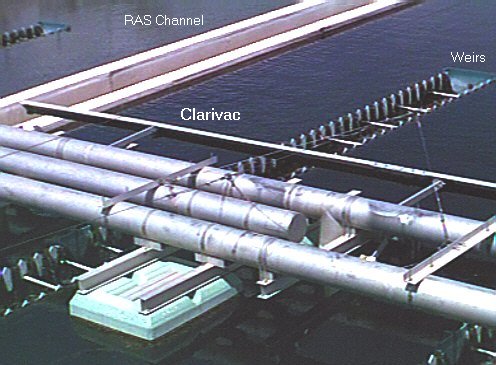
Effluent Structure...
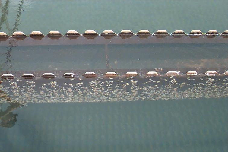
Scum Baffle...
In many well - operating secondary plants, very little scum is formed in the secondary clarifiers. With respect to get scum
and floating material free effluent, a scum baffle is mounted in front of the weir. Scum collected at the water surface
should be removed. Typical scum removal equipment includes beach- and scraper-type, rotating pipe-through skimmer, and
slotted pipes. Scum is usually disposed of with the sludge produced at the plant; however, separate scum disposal is used
by many plants.

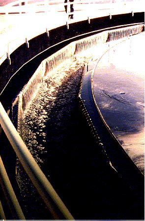
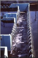
 Effluent Weirs...
When density currents occur in a secondary clarifier, mixed liquor entering the tank flows along the tank bottom until it
encounters a counter - current pattern or an end wall. When the mixed liquor encounters an end wall, it tends to mound up
and may be discharged over the effluent weirs, especially those located at the end of the tank. With low surface loadings
and weir rates, the placement of the weirs in small tanks does not significantly affect the performance of the clarifier.
Circular clarifiers are manufactured with overflow weirs located near both the center and the perimeter of the tank.
Effluent Weirs...
When density currents occur in a secondary clarifier, mixed liquor entering the tank flows along the tank bottom until it
encounters a counter - current pattern or an end wall. When the mixed liquor encounters an end wall, it tends to mound up
and may be discharged over the effluent weirs, especially those located at the end of the tank. With low surface loadings
and weir rates, the placement of the weirs in small tanks does not significantly affect the performance of the clarifier.
Circular clarifiers are manufactured with overflow weirs located near both the center and the perimeter of the tank.
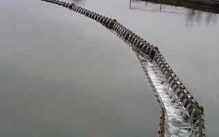
Effluent weirs...
Weir - loading rates are commonly used in the design of clarifiers, although they are less critical in clarifier design than
hydraulic overflow rates. Weir - loading rates for rectangular shaped weirs, used in large tanks should preferably
not exceed 375 m3/m.day of weir at maximum flow when located away from the upturn zone of the density
current, or 250 m3/m.day when located within the upturn zone. In small tanks, the weir - loading rate
should not exceed 125 m3/m.day at average flow or 250 m3/m.day at maximum flow. For
triangular shaped weirs hydraulic design is carried out on the basis of weir load. Weir load should be as possible
as low.
Effluent Launder...
Effluent launder is used to collect flow passing over the weirs. Launder should have a certain slope through the main outlet
structure.
"Effluent Structure"...
Short Circuiting...
In consequence of short-circuiting, the feed prematurely reaches the effluent and the underflow. Short-circuiting occurs
in two modes which are referred to as ; (1) Short-circuiting into the effluent and (2) Short-circuiting into the underflow
(sludge). While "effluent short-circuiting" is reasonably well described and treated in most final clarifiers,
"underflow short-circuiting" is frequently not correctly understood and described.
"Short - Circuiting Zones"...
Underflow short-circuiting results from insufficient capacity of sludge transport. Then, instead of withdrawing the sludge
bottom concentration, a mixture of the bottom and the inlet concentration is withdrawn. Fraction of the short-circuited flow
with the incoming concentration of suspended solids Xa is noted z and called
"short-circuiting coefficient" (with values 0 - 1). From mass balance around the sludge outlet point ;
(Qr) (Xr) = (z) (Q0) (Xa) + (1 - z) (Qr) (Xb)
Equation can be rearranged to ;
z = (Xr - Xb) / (Xa - Xb)
The advantage of this approach is that z can be calculated from routinely measured
concentrations Xr and Xa. The bottom sludge concentration can be easily measured. Early expression
of the short-circuiting coefficient comes from Günthert (1984), who expressed both the recycle ratio and the short-circuiting
coefficient in percents. If modified to fractions, his equation is ;
k = 0.2347 ln (R) + 0.3475
where, by Günthert's definition ;
k = Qsc / [ (1 + R) (Q0) ]
and Qsc is the short-circuiting flow. The relation between z and k is ;
z = (k) (1 + R) = [ 0.2347 ln (R) + 0.3475 ] / (1 + R)
Though Günthert claimed that equation located above is valid from R 0.15 to 1.83, the values of Qsc / Q0
are negative below R approx. 0.22 and greater than 1 above R = 1.4. In his field measurements at several plants, the clarifier
Buchloe II, which was about average of all, produced typically Xr ~ 6 g / L and Xb ~ 13 g / L. It has
to be noted that the bottom concentration would double the recycled concentration at a poorly designed and operated clarifier
only. German guideline A131 recommends to calculate the sludge blanket height from the bottom concentration ; but fails
to offer methodology how to calculate the bottom concentration. Instead, it recommends to use Xr ~ 0.7 Xb
(or 0.5-0.7), regardless of R. Interpretation in relation to short circuiting is shown in the figure.
"The Relationship Between z and R"...
The value of z depends on a number of factors. Those controllable are ; bottom slope,
shape, height and rotational speed of scrapers and recycle ratio. It can be seen from the figure that the main discrepancies
are at low recycle ratios. Günthert's prediction is too low, that of A131 too high. More research is needed. It has been
found that new clarifiers at the treatment plant in Prague (diameter 44 m) reveal Xr / Xb > 0.9,
indicating very small z (about 0.1). The smaller z, the shallower
the sludge blanket and the higher the limiting load.
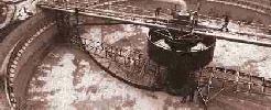
 Bottom Scraper...
Traditional design can be characterized by ; (1) small number of arms, (2) slow revolutions, (3) too shallow scrapers
(and too shallow clarifiers) and (4) inappropriate shape of scrapers. Advanced design combines full length (radius) and
partial length arms to provide sufficient energy to overcome tixotropic properties of activated sludge and sufficient
transport of sludge to minimize the difference between the bottom and the recycled TSS and thus sludge blanket depth.
Two-speed or variable speed arms are used as well. Some principles of new design are shown in the figure.
"Mean Interval of Rotation at Peripheral Velocity 0.04 m / s"...
Bottom Scraper...
Traditional design can be characterized by ; (1) small number of arms, (2) slow revolutions, (3) too shallow scrapers
(and too shallow clarifiers) and (4) inappropriate shape of scrapers. Advanced design combines full length (radius) and
partial length arms to provide sufficient energy to overcome tixotropic properties of activated sludge and sufficient
transport of sludge to minimize the difference between the bottom and the recycled TSS and thus sludge blanket depth.
Two-speed or variable speed arms are used as well. Some principles of new design are shown in the figure.
"Mean Interval of Rotation at Peripheral Velocity 0.04 m / s"...
"Scraper Characteristics"...
(A) Straight plow scrapers were popular but not effective for any type of solids. (B) Curved plow scrapers are convenient
at many situations. Fixing them to the arm is relatively complicated and thus spiral scrapers took over. (C) Variable angle
spiral scrapers are popular in Europe. They are easy to assemble and less expensive than previous types. (D) Logarithmic
spiral scrapers are increasingly popular. Angle of attack is typically 30 - 40 º.
Industrial clarifier with peripheral drive, two full and two short arms, equipped with logarithmic spiral. Single weir
effluent launder mounted on the inner side of the wall; Stamford baffle. Weir loading rate was not considered to be
a valid parameter for design.
 Parameters Characterising the Settling Process...
There are numerous parameters that influence the settling process. Some of them are hidden in different macroscopical tests,
that do not explain their properties. A selection of these parameters is discussed below. Sludge volume index, SVI, is a
rough measure of the sludge settling properties. The test shows how far the thickening process has reached after 30 minutes.
The settling velocity as a function of time is not monitored. Therefore, it is possible that two kinds of sludges with the
same SVI show different settling properties. SVI is a standard test that is performed regularly on most major plants. Though
it does not supply any complete information about the sludge it is a guideline for more sophisticated tests. The main purpose
of the settling process is to separate sludge and water. Information on how this aim is fulfilled is essential for the plant
operation. This information is obtained with special gauges for the concentration of suspended solids in the effluent, here
called Cout. The measurements are not simple and may imply some problems caused by failing gauges. Even
if it is not common to find on-line sensors for secondary clarifier effluent, this work can prove the added value of having
such a facility.
Parameters Characterising the Settling Process...
There are numerous parameters that influence the settling process. Some of them are hidden in different macroscopical tests,
that do not explain their properties. A selection of these parameters is discussed below. Sludge volume index, SVI, is a
rough measure of the sludge settling properties. The test shows how far the thickening process has reached after 30 minutes.
The settling velocity as a function of time is not monitored. Therefore, it is possible that two kinds of sludges with the
same SVI show different settling properties. SVI is a standard test that is performed regularly on most major plants. Though
it does not supply any complete information about the sludge it is a guideline for more sophisticated tests. The main purpose
of the settling process is to separate sludge and water. Information on how this aim is fulfilled is essential for the plant
operation. This information is obtained with special gauges for the concentration of suspended solids in the effluent, here
called Cout. The measurements are not simple and may imply some problems caused by failing gauges. Even
if it is not common to find on-line sensors for secondary clarifier effluent, this work can prove the added value of having
such a facility.
Diagnosis may also rely on suspended solids concentrations at various locations. Those of most interest are the suspended
solids in the return sludge flow, Cr, in the bioreactor, Cbio, as well as in the
influent to the settler, Cset. The suspended solids concentrations in the bioreactor are measured on-line
at many plants. Usually one would like to quantify the suspended solids concentration in weight per volume, e.g. mg / L.
However, due to the principles of the measurements it is instead given as turbidity. Measurements of suspended solids are
usually noisy and may include extreme changes, e.g. during a wash-out period. Sometimes it has to be thoroughly tested and
reconsidered before used for any diagnosis purpose, otherwise it is easy to end up with wrong conclusions.
The hydraulics in the plant has a crucial influence on the settling process. Variations of the influent flow, Qin,
will propagate through the plant and affect the hydraulic conditions in the settler unit. The flow into the settler unit,
Qset, is not identical with the influent flow to the plant. It will be subdued and delayed depending on
the configuration of the plant. When Qset is not measured it must be approximated or reconstructed so
that an adequate opinion on the settling hydraulic conditions can be obtained. Due to practical reasons the effluent flow,
Qout, might be measured instead. The under-flow in the settler affects the hydraulics as well. It is well
known that variations in the return sludge flow, Qr, will propagate through the aeration step and further
on hit the settler, and consequently the clarification process. Other phenomena, that previously have been disregarded,
appear at rapid changes in the settler under-flow.
The level of the sludge blanket is rarely measured on a routine basis, but might append useful information on the settling
process. Due to limitations in presently known models for the thickening process it is difficult to estimate the level of
the sludge blanket. Available gauges have shown poor performance, and they are still too expensive to be of interest for
minor or medium size plants. For this reason it is not recommended that methods for diagnosis rely on measurements of the
sludge blanket, even if the information is valuable when it is present. There are several other factors or phenomena that
influence the settling process. The effects of most biological activities are for example still unknown. However, some are
known and have even been incorporated in settling models.
Solid Content Measurement in Wastewater Treatment Plants...
Introduction...
Nowadays the operation of a sewage plant is subject to very strict criteria. Expectations are always rising. One is the
waste water treatment performance regarding the goverment regulations, the other is an economical ideal operation. Cause
of behaviour of municiple producers of waste water and on the constantly growing number of industrial producers of waste
water, static operations are in most cases not satisfactory. Besides the conventional controls depending on time, further
parameters such as suspended solids, sludge blanket level or sludge volume become more and more important. One of the main
advantages of continous process analyses, compared to the laboratory analysis, is the fact that process parameters are
always available.
The use of process measuring devices for above mentioned parameters gives better insight in the operating procedures. It
allows a quick manual adjustment of the process, a partial and favorable automatization as well as continuous reporting.
Especially the step to automatization leads to a significant improvement regarding stability and continuity of the waste
water treatment procedure.
Measuring Principle of Turbidity and Suspended Solid Measuring Systems...
Up to now, there are no automatic devices for determination suspended solid with the graphimetrical method. Suspended solid
measurement systems (continuous), which are very common in practice, are generally based on the principle of light
extinction.
Extinction / Absorption of Light...
If a focused light beam (Io) is sent through a liquid suspension, its intensity is reduced by absorption and a scattering
(IS) effect. The intensity of the transmission light (IT) can be measured. The extinction E is defined as follows ;
E = ln ( I o / I T ) or I T = I o e - E
The Law of Lambert - Beer...
I T = I o e - ( A ) ( D ) or I T = I o e - ( x ) ( C ) ( D )
where ; A : diffusion / absorption factor, D : path - length penetrated by light, C : concentration of suspension and
x : optical diameter of the suspended particles.
Application Examples - Control Strategies...
Simple control : Is an intervention into a process without continuous feedback of the process (feed forward). An
example is the control of return activated sludge proportional to the waste water inlet.
RV = QRS / Q
where ; QRS : amount of return activated sludge, Q : waste water inflow and RV : percentage of return activated sludge.
Advanced control : Is a procedure where a parameter (x), which has to be controlled, is continuously monitored. This
actual value is compared with a setpoint (W). Depending on the result of this comparison, the process is adjusted with the
goal to make (X) equal to (W). This happens in a closed circle, the automatic control system.
4 - Beam alternating light principle : In order to compensate light weakening which is caused by soiling (dirt) on
the probe windows, Staiger Mohilo uses a multibeam measurement system. The 4-beam alternating light procedure is based on
pulsed monochromatic light (near infrared area). The use of two infrared diodes and two receiving elements allows a triple
quotient calculation out of the single measured values, and therefore a compensation of dirt and aging of the components
can be realized.
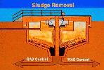
Automated Primary Sludge Outlet...
Goal of this control is to thicken the sludge in the funnels of the primary settling tanks as much as possible. On the one
hand, in view of the following sludge treatment, e.g. hydraulic capacity of the digester, heating of the digesting room,
gas production and sludge dewatering, a high thickening grade is aimed for. On the other hand, it is also mandatory to
avoid anti-aerobic situation and an emission of the sludge into the biological stage. Figure shown below shows a possiblitiy
of control which exceeds the frame of an operation mode that depends only on time. When a certain sludge level is reached,
the outlet procedure can be started. A few minutes later after opening the valve a suspended solid meter mounted in the
discharge pipe will start measuring. This system will close the sludge discharge valve when the predetermined limit
concentration is reached. A short time delay is necessary since water has to be expected directly after opening of the
valve (settling effect).
Figure given below shows the sludge concentration during a discharge period.
Control of Return Activated - Waste Activated Sludge...
The performance of most sewage plants mainly depends on the efficiency of the biological stage. The suspended solid content
of activated sludge, sludge volume, as well as the age of sludge plays an important role. The conventinal methods of evaluating
suspended solid and sludge volume by taking samples and laboratory analysis are subject to major time delays, and therefore
not usable for control. In addition to that the control becomes dependend on the operator.
Examples of Control Strategies...
- A constant percentage of return activated sludge is adjusted based on measuring the inflow of the sewage plant. Here a
changing concentration of biological substance in the areation basin and in the return activated sludge is not taken into
account.
- Better is the adjustment of a constant suspended solid content in the areation basin. Basing on a permanently working
suspended solid measurement in the areation basin, the amount of return activated sludge is adjusted by a step-by-step
control. In order to consider time delay in the event of rainfall, it is now useful to implement also the signal of the
inlet flow as feed-forward. That means that the control signal, which results from the measurement of suspended solid, is
effected by inflow measurement. This has the advantage, that also in cases of fluctuating inflow and changing sludge, a
constant amount of biological mass in the areation basin is available.
- The discontinuous outlet of waste sludge can be realized according to the amount of suspended solids in return activated
sludge. The waste activated sludge pumps can be activated per suspended solid limit switch. However, a possible sludge
emission out of the secondary clarifier in case of bad settling characteristics remains unconsidered. A continous measuring
of suspended solid in the return activated sludge pipe offers also the possibility to use the signal for the optimization
of return activated sludge control.
- Continuously operating sludge level detection systems on the scraper bridge of the secondary clarifier detect the sludge
level. The waste sludge pumps are activated by min./max. limit switch. Measuring systems which provides additional to the
height signal also of an signal for suspended solid offer the possibility of frequently monitoring a concentration profile.
The settling of the sludge in the secondary clarifier becomes transparent.
"Return & Waste Activated Sludge Control - 1"...
- Control of return activated- and waste activated sludge refering to suspended solid in the areation basin, as well as
sludge volume become more and more popular. The reason for this is, that the two stage plants (denitrification, nitrification)
requires also a certain age of sludge. The sludge volume has a relationship to sludge age.
"Return & Waste Activated Sludge Control - 2"...
Optimized Dosage of Flocculents in the Process of Sludge Dewatering...
In many cases the sludge is first chemically conditioned in order to accelerate dewatering and to raise efficiency of the
centrifuges. Here, organic substances such as polyelectrolydes (polymeres) are used. Goal is now on the one hand to obtain
more information from the process by employing analysing instruments. On the other hand to build up a control loop. Taking
into account that the dewatering result is mostly effected by the kind and amount of flocculent, by the dry mass (flow
multiplied with suspended solid) and especially by the nature of the sludge itself, the importance of continuous measuring
becomes obvious. The efficency of the flocculant dosage is changing with the different incredients of the sludge.
(a) Control strategy based on constant dry mass : A first step towards a "controlled operation" is the
control of the arriving dry mass. Here, the multiplication resulting from sludge flow measurement and suspended solid
measurment is kept on a constant level. Such a method controls the dry mass, however not the effect of chemicals on the
changing sludge nature. This represents a feed-forward control without any feedback from the dewatering result. As a
consequence, this strategy is commonly used in cases where no flocculents are added.
(b) Control strategy with measuring of turbidity in the centrate : Basis of this strategy is ; A turbidity meter in
the centrate. For the measuring it has to be taken into account that the measuring probe is installed in a deareation vessel
which has the task to eliminate foam and air-bubbles. The flocculent is dosed according to turbidity in the centrate. In
order to take care of sudden changing dry mass, the dry mass signal is switched as feed forward.
"Remote Control System for Sludge Conditioning"...
However, this does not represent an optimisation yet. It means in general that with an increasing dosage of flocculents
the turbidity in the centrate decreases. In case of over-dosing the turbidity increases again. Furthermore, it has to be
considered that with a beginning dosage of flocculent the turbidity decreases relatively much. This proportion reverses
with increasing dosage, since relatively higher dosing only effects a lower decrease of turbidity. This has the result
that the optimum for a dosage of flocculent is not necessarly equal to the lowes turbidity. Often it is useful to determine
a economic optimum. It specifies a relation of turbidity decrease and flocculent dosage. That means the control parameter
is not turbidity of the centrate, but the slope of the curve which represents the relation between turbidity decrease and
flocculent dosage. The calculation runs as follows ;
| Actuall value of slope = |
 |
So as set point the slope is used, not the turbidity.
"Turbidity vs Feed Flocculent"...
It goes without saying that the above mentioned concept can only touch the complete range of possibilities.