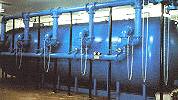
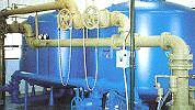
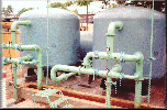
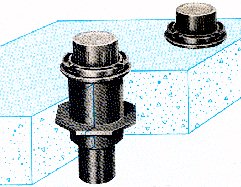
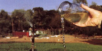
Location of Sand Filter and Chlorine Contact Tank...

"Location of the Units"...

Sand Filtration...

The objective of the filtration process, which is a physical treatment process, is to remove non - settleable particles and microorganisms. (1) The removal mechanisms are straining, interception, and flocculation / sedimentation. (2) As more particles are removed, the headloss in the filter will increase. Eventually (6 - 24 hours of use) the filters will reach a terminal headloss and will need to be backwashed. (3) Backwashing consists of reversing the flow through the filter at a high rate, suspending and scouring the filter media. At the end of backwashing, the media will settle back into the normal configuration.


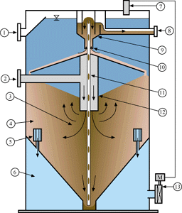
Gravity Sand Filter
  1. OverFlow
  2. Filter Influent
  3. Coarse Media
  4. Fine Media
  5. Filtrate Nozzles
  6. Filtrate Chamber
  7. Level Controller
  8. Filter Reject
  9. Washbox
  10. Counter-Current Washer
  11. Airlift
  12. Central Feed Chamber
  13. Actuated Valve

Application Loading Rate (gpm /ft2) Influent Solids (TSS mg / L) Filtrate (TSS mg / L)
Tertiary Filtration 3 to 11 20 to 150 1 to 10
Algae Removal 3 to 4 20 to 150 1 to 10
Surface Water Direct Filtration 3 to 8 10 to 200 NTU < 1 NTU
Metal Hydroxides 3 to 7 20 to 100 1 to 5
Phosphorus Removal 3 to 7 20 to 100 1 to 3 (TSS), < 0.3 P

Filter Characteristics...

Filters are classified by loading rate;

"Loading Rates of Sand Filters"...

Filter media are chosen for their headloss and settling velocity characteristics. Important filter media properties include grain size distribution, particle density, shape, and porosity. Filters often contain more than one media type. For example, dual - media, rapid sand filters have a layer of anthracite coal overlying sand.

Filter Design Parameters...

Filter design parameters can be listed as ; (1) Loading rate, (2) dimensions of filter box, (3) filter media characteristics / configuration, (4) backwash rate, (5) configuration of washwater troughs and (6) disposal of washwater.


Continuous Backwash Gravity Sand Filter...

Description of Operation...

The Centra-flo Gravity Sand Filter is a downflow, dynamic bed filter that provides a continuous supply of filtered water without interruptions of backwash cleaning cycles. Centra-flo can be used whenever an application requires granular media filtration for the removal of colloidal and suspended solids. Influent enters the center of the filter through a feed chamber and flows downward through layers of increasingly finer sand. Filtered water is collected through multiple filtrate nozzles around the periphery before exiting the filter. Solids captured in the filter bed are drawn downward with the sand into the suction of an airlift pump. The turbulent, upward flow in the airlift provides a scrubbing action that effectively separates the sand and solids before discharging into the filter washbox. The washbox is a baffled chamber that allows for counter-current washing and gravity separation of the cleaned sand and the concentrated waste solids. This process is accomplished by utilizing filtered water to clean the contaminated sand. Regenerated sand is returned to the top of the filter bed, and the waste solids, or "reject", is piped to a suitable disposal point.

"Centra-flo Gravity Sand Filter"...

Filter Media...

Filter media is the key to successful filter performance. An "ideal" filter would utilize the entire depth of the bed to maximize particulate removal and minimize headloss. The Centra-flo Gravity Sand Filter utilizes a system that approaches these ideal conditions. The Centra-flo Gravity Sand Filter employs a coarse-to-fine sand gradation. The coarsest sand "rolls" to the center of the filter cell while the finest particles remain at, or near, the periphery of the filter bed. The grading process is the result of gravity's effect on the varying sizes of the sand as it seeks its natural angle of repose. The coarse-to-fine gradation is maintained throughout the depth of the filter as the airlift pump continually removes the dirtiest sand from the lower cone and distributes it in the washbox for cleaning. Filter media can be tailored to suit individual application requirements. Sand sizes typically range from 0.5 mm to 3.0 mm.


Airlift Sand Cleaning System...

Sand and accumulated solids are continuously removed from the bottom of the filter and transported to the washbox for cleaning and separation by means of an airlift pump. This pump consists of a vertical pipe, open at both ends, with the lower end submerged at the bottom of the filter bed. Compressed air is introduced near the bottom of the pipe at a rate of 1 to 4 scfm at 30 psi. This reduces the density of the mixture relative to the outside of the pipe, and causes the mixture to rise to the top where it is discharged into the washbox. By properly combining the pipe size and the air flow, sand is transported up the airlift with sufficient turbulence to scour waste solids from the sand. For most applications, the air rate is designed to provide a sand bed turnover rate of every 4 hours or greater depending on the particular application. The air flow rate can easily be adjusted based on specific site conditions.

Washbox Cleaning System...

The airlift pump discharges into the center of the washbox where the waste solids and media are separated. Solids removal is accomplished as a small portion of filtered water flows up into the washbox in an attempt to equalize the weir controlled differential water level between the filter tank and the washbox. The upward velocity of the filtrate keeps the low density solids in suspension so they can be discharged over the reject weir, while the higher density silica sand settles through the counter-current flow to the top of the sand bed. For most applications, the reject rate will range from 2% to 5% of the total flow.

"Process Schematic"...


Filtrate Chambers...

Each filter is equipped with multiple filtrate chambers that act as a barrier between the filtrate and the moving sand bed. The filtrate collection system consists of a suitable number of individual nozzles connected to a common manifold or filtrate well. The nozzles are constructed of various materials of construction to suit the application. The trapezoidal bars, or "wires" have clear openings of 0.008". The slotted opening are oriented on a vertical axis, and located in the periphery of the lower portion of the sand bed. Filtrate enters the chamber through the nozzle face and is piped out of the filter. The clear opening of the nozzle is designed to be no greater than one half the size of the finest granular media. The trapezoidal shape of the slot opening prevents the sand particles from becoming lodged between the adjacent wires.

Flow Control...

Flow passes through the Centra-flo Filter by gravity. Filter operation will be controlled by the liquid level in the filter tank using an pneumatic float displacer type level sensor. An automatic effluent control valve will be provided with an pneumatic positioner to regulate the degree of opening in response to a 3 to 15 psi signal from the level sensor. A change in signal will result in a corresponding change in the degree of valve opening or closing. Flow control system will be self-contained and may require manual adjustments to fine tune the system. Each filter will be furnished with an operator's control station equipped with a manual shut off valve, air regulator, (2) air filters, rotameter, (2) pressure gauges, and all other controls necessary for operation of the filter's airlift.

"Instrumentation"...

Headloss...

Filter headloss varies as a function of solids loading, flow rate, and water temperature. In the Centra-flo Gravity Sand Filter, the available headloss is defined as the difference in water levels between the nominal filter water level and the water level in the downstream unit process. The recommended design headloss for a Centra-flo Gravity Sand Filter is 36" or greater. This will insure that the filter will have enough driving head to overcome the friction losses through the filter media, piping, filtrate nozzles, and accumulated solids. Normal operating headloss ranges from 6" to 24".

Standard Models...

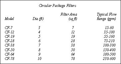
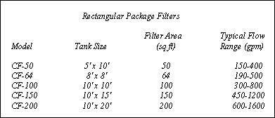
The Centra-flo Gravity Sand Filters are available for use in fiberglass, steel, stainless steel, or concrete basins. Except for tank materials, most models vary only in tank plan area. Each Centra-flo Package Filter consists of one to eight filter modules operating simultaneously within a common tank. Installations requiring multiple-module filters are available with individual module sizes of 25 ft2 (steel tank package filters) and 50 ft2 (concrete tanks).

Circular Package Filters...


Rectangular Package Filters...


Larger, customized filter arrangements are also available to suit virtually any size treatment plant. These filters will generally utilize concrete basins with pre-fabricated internal components. Designs for concrete tanks are available upon request and are likely to be site specific.

Surface Loading...

The Centra-flo Gravity Sand Filter is nominally rated from 3 to 7 gpm/ft of filter surface area. However, based on filtration characteristics of the solids present, higher or lower rates may be recommended. Before filter performance can be realistically predicted, the amount of filterable solids, the variability of their quality, the fraction to be removed, and their characteristics must be accurately determined.

Additional information will be required based on the type of application to be considered.

Municipal Water...

Inquiries regarding surface water applications should include information on suspended solids, alkalinity, hardness, pH, turbidity, color, and minimum water temperature. Ground water inquiries should also include information on hardness, iron, and manganese concentration. All water treatment applications will require a careful review of existing or proposed coagulation, rapid mix, and flocculation facilities. A description of the preferred primary coagulant and any proposed flocculant/filter aids should also be provided.

Municipal Waste...

Municipal wastewater treatment applications should include a description of the type of secondary treatment plant (e.g. activated sludge, trickling filter, phys-chem) and the type of upstream unit process (e.g. secondary clarifier, aerated lagoon). Special attention should be given to applications involving filtration of lagoon effluents because of possible problems related to algae blooms.

Industrial Process Water...

Industrial water filtration applications require the same information as municipal water projects. Special attention should be given to temperature, flow variation, pH, and corrosivity. It is usually helpful to know what, if any, unit process will follow filtration such as reverse osmosis, ion change, etc.

Industrial Waste...

Industrial waste applications require careful and complete review. As with municipal waste, a good description of the upstream treatment process is required. A complete waste analysis including oil and grease concentrations should be obtained. The pH and temperature should be delineated. Flow characteristics should also be reviewed, and the possibility and effects of upstream process upsets considered.