Conventional Water Treatment Processes...
1. Coagulation...
Surface waters must be treated to remove turbidity, color and bacteria. The object of coagulation (and subsequently flocculation) is to turn the small particles of color, turbidity and bacteria into larger flocs, either as precipitates or suspended particles. These flocs are then conditioned so that they will be readily removed in subsequent processes. Technically, coagulation applies to the removal of colloidal particles. We define coagulation as a method to alter the colloids so that they will be able to approach and adhere to each other to form larger floc particles.
Colloid Stability...
Before discussing colloid removal, we should understand why the colloids are suspended in solution and cannot be removed
by sedimentation or filtration. Very simply, the particles in the colloid range are too small to settle in a reasonable
time period and too small to be trapped in the pores of a filter. For colloids to remain stable they must remain small.
Most colloids are stable because they possess a negative charge that repels other colloids particles before they collide
with one another.
Colloid Destabilization...
Since colloids are stable because of their surface charge, in order to destabilize the particles, we must neutralize
this charge. Such neutralization can take place by addition of an ion of opposite charge to the colloid. Since most
colloids found in water are negatively charged, the addition of sodium ions (Na+) should reduce the charge.
As we would have predicted, then higher the concentration of sodium we add, the lower the charge, and therefore the lower
the repelling forces around the colloid. If, instead of adding a monovalent ion such as sodium, we add a divalent or trivalent ion, the charge is reduced even faster. In fact, it was found by schulze and Hardy that one mole of a trivalent
ion can reduce the charge as much as 30 to 50 moles of a divalent ion and as much as 1,500 to 2,500 moles of a monovalent ion.
Coagulants...
The purpose of coagulation is to alter the colloids so that they can adhere to each other. During coagulation a positive
ion is added to water to reduce the surface charge to the point where the colloids are not repelled from each other. A coagulant is the substance (chemical) that is added to the water to accomplish coagulation. There are three key properties
of a coagulant :
1. Trivalent cation : As indicated in the last section, the colloids most commonly found in natural waters are negatively charged, hence a cation is required to neutralize the charge. A trivalent cation is the most efficient cation.
2. Nontoxic : This requirement is obvious for the production of a safe water.
3. Insoluble in the neutral pH range : The coagulant that is added must precipitate out of solution so that high concentrations of the ion are not left in the water. Such precipitation greatly assists the colloid removal process.
The two most commonly used coagulants are aluminum (Al+3) and ferric iron (Fe+3). Both meet the above three requirements and their reactions are outlined here.
Aluminum...
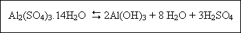
Aluminum can be purchased as either dry or liquid alum [Al2(SO4)3.14H2O]. When alum is added to a water containing alkalinity, the following reaction occurs :

Such that each mole of alum added uses six moles of alkalinity and produces six moles of carbon dioxide. The above
reaction shifts the carbonate equilibrium and decrease the pH. However, as long as sufficient alkalinity is present
and CO2 is allowed to evolve, the pH is not drastically reduced and is generally not an operational problem.
When sufficient alkalinity is not present to neutralize the sulfuric acid production, the pH may be greatly
reduced :
If the second reaction occurs, lime or sodium carbonate may be added to neutralize the sulfuric acid. Two important factors in coagulant addition are pH and dose. The optimum dose and pH must be determined from laboratory tests. The optimal pH
range for alum is approximately 5.5 to 6.5 with adequate coagulation possible between pH 5 to pH 8 under some conditions.
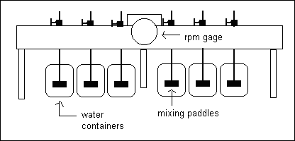
One of the most common methods to evaluate coagulation efficiency is to conduct jar test. Jar tests are performed in an apparatus such as shown in figure given below. Six beakers are filled with water and then each is mixed and flocculated uniformly by a gang stirrer. A test is often conducted by first dosing each jar with the same alum dose and varying the
pH in each jar. The test can then be repeated by holding the pH constant and varying the coagulant dose.
Iron...
Iron can be purchased as either the sulfate salt (Fe2(SO4)3.xH2O) or the
chloride salt (FeCl3.xH2O). An example of the reaction of FeCl3 in the presence of alkalinity
is :
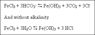
Forming hydrochloric acid which in turn lowers the pH. Ferric salts generally have a wider pH range for effective
coagulation than aluminum, that is, pH ranges from 4 to 9.
Coagulant Aids...
The four basic types of coagulants aids are pH adjusters, activated silica, clay and polymers. Acids and alkalies are
both used to adjust the pH of the water into the optimal range for coagulation. The acid most commonly used is sulfuric
acid and the most commonly base is lime [Ca(OH)2]. When activated silica is added to water, it produces a stable solution that has a negative surface charge. The activated silica can unite with the positively charged aluminum or with
iron flocs, resulting in a larger, denser floc that settles faster and enhances enmeshment. The addition of activated silica is especially useful for treating highly colored, low-turbidity waters cause it adds weight to the floc. However, activation of silica does require proper equipment and close operational control and many plants are hesitant to use it. Clays can act much like activated silica in that they have a slight negative charge and can add weight to the flocs. Clays are also most useful for colored, low turbidity waters.
Polymers can have a negative charge (anionic), positive charge (cationic), positive and negative charge (polyamphotype)
or no charge (nonionic). Polymers are long-chained carbon compounds of high molecular weight that have many active sites.
The active sites adhere to flocs, joining them together and producing a larger tougher floc that settles better. This
process is called interparticle bridging. The type of polymer, dose and point of addition must be determined for each
water and requirements may change within a plant on a seasonal, or even daily basis.
Factors Which Affect the Coagulation...
The factors which affect coagulation are :
(i) Kind of coagulant
(ii) Quantity of coagulant
(iii) Amount, character of colour and turbidity of water
(iv) pH value of water
(v) Time of mixing and flocculation
(vi) Temperature
(vii) Violence of agitation
Function of Coagulation...
These are to remove :
(i) Turbidity
(ii) Organic and inorganic matter
(iii) Colour
(iv) Harmful and other pathogenic bacteria
(v) Algae, planktons and other organisms
(vi) Taste and odour producing substances
Problem 1...
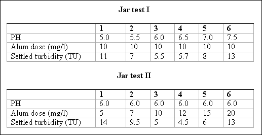
Two sets of jar tests were conducted on a raw water containing 15 TU and an HCO3- alkalinity concentration of 50 mg/l expressed as CaCO3. Given the data below, find the optimal pH, coagulant dose, and
the theoretical amount of alkalinity that would be consumed at the optimal dose.
2. Flocculation...
Clearly, if the chemical reactions in coagulating a water are going to take place, the chemical must be mixed with the
water. Mixing as it is called is the process whereby the chemicals are quickly and uniformly dispersed in the water.
During coagulation the chemical reactions that take place in rapid mixing form precipitates, such as aluminum hydroxide or iron hydroxide. The precipitates formed in these processes must be brought into contact with one another so that they can agglomerate and form larger particles, called flocs. This contacting process is called flocculation and is accomplished by slow, gentle mixing.
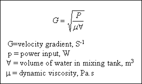
In the treatment of water and wastewater the degree of mixing is measured by the velocity gradient, G. The velocity
gradient is best thought of as the amount of shear taking place; that is, the higher the G value, the more violent the mixing. The velocity gradient is a function of the power input a unit volume of water. It is given by :
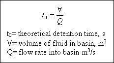
From literature, experience, laboratory or pilot plant work it is possible to select G value for a particular application. The total number of particle collisions is proportional to G.t0, where t0 is the detention time in
the basin. For time dependent reactions, the time that a fluid particle remains in the reactor obviously affects the degree
to which the reaction goes to completion. In ideal reactors the time in the reactor (detention time or retention time) is defined as :
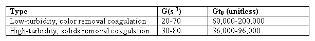
While rapid mix is the most important physical factor affecting coagulant efficiency, flocculation is the most important factor affecting particle removal efficiency. The objective of flocculation is to bring the particle into contact so that they will collide, stick together, and grow to size that will readily settle. Enough mixing must be provided to bring the floc into contact and to keep the floc from settling in the flocculation basin. Too much mixing will shear the floc
particles so that the floc is small and finely dispersed. Therefore, the velocity gradient must be controlled within a relatively narrow range. Flexibility should also be built into the flocculator so that the plant operator can vary the G value by a factor of two to three. The heavier the floc and the higher the suspended solids concentration, the more mixing
is required to keep the floc in suspension. This is reflected in table given below :
Flocculator...
Flucculation is normally accompolished with an axial – flow impeller), a paddle flocculator or a baffled chamber. The baffle-mixing basin is called also “up and down baffle mixing basin”. In this, the water (with coagulant) enters at P,
flows down through the channel under baffle, rise up through the channel, sweeps across the top of baffle and then flows through other channels until it finally flows out at Q. The velocity is nearly 30 cm/s.
Power Requirements...
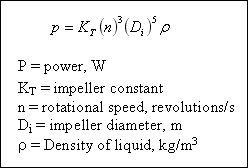
In the design of mixing equipment for rapid – mix and flocculation tanks, the power imparted to the liquid in a baffled
tank by an impeller may be described by the following equation for fully turbulent flow developed by Rushton :
Mixing, flocculation and clarification may be conducted in a single tank. The influent raw water and chemicals are mixed in the center cone-like structure. The solids flow down under the cone. As the water flows upward, the solids settle to form a sludge blanket. This design is called an upflow solids-contact basin. The main advantage of this unit is its reduced size.
Problem 2...
The city of Redpherric is planning for the installation of a water treatment plant to remove iron. A low-turbidity iron coagulation plant has been proposed with the following design parameters :
Q = 2 m3 / sec
Rapid mix t0 = 10 sec
Rapid mix G = 1,000 sec-1
Floc t0 = 20 min
Floc G = 30 sec-1
Water temperature = 18 OC
Design the rapid-mix and flocculation basins and size of the equipment.
3. Sedimentation...
Particles that will settle within a reasonable period of time can be removed in a sedimentation basin (also called clarifier). Sedimentation basins are usually rectangular or circular with either a radial or upward water flow pattern. Regardless of the type of basin, the design can be divided into four zones; inlet, settling, outlet, and sludge storage.
The purpose of the inlet zone is to evenly distribute the flow and suspended particles across the cross section of the settling zone. The inlet zone consists of a series of inlet pipes and baffles placed about 1 m into the tank and extending the full depth of the tank. The outlet zone is designed so as to remove the settled water from the basin without carrying away any of the floc particles. A fundamental property of water is that the velocity of flowing water is proportional to
the flow rate divided by the area through which the water flows, that is :
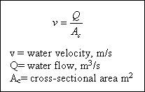
To remove the water from the basin quickly, it is desirable to direct the water into a pipe or small channel for easy transport, which will produce a significantly higher velocity. If a pipe were to be placed at the end of the sedimentation basin, all the water would rush to the pipe. This rushing water would create high velocity profiles in the basin, which
would tend to raise the settled floc from the basin and into the effluent water. This phenomenon of washing out the floc
is called scouring, and one way to create scouring is with an improper outlet design. Rather than put a pipe at the end of the sedimentation basin, it is desirable to first put a series of troughs, called weirs, which provide a large area for the water to flow through and minimize the velocity in the sedimentation tank near the outlet zone. The weirs then feed into a central channel or pipe for transport of the settled water.
Sedimentation Concepts...
There are two important terms to understand in sedimentation zone design. The first is the particle (floc) settling
velocity, vs. The second is the velocity at which the tank is designed to operate, called the overflow rate,
v0. The easiest way to understand these two concepts is to view a upward-flow sedimentation tank.
In this design, the particles fall downward and the water rises vertically. The rate at which the particle is settling downward is the particle-settling velocity, and the velocity of the liquid rising is the overflow rate. Obviously, if a particle is to be removed from the bottom of the clarifier and not go out in the settled water, then the particle-settling velocity must be greater that the liquid-rise velocity (vs,nu v0). If vs, is greater
than v0, one would expect 100 percent particle removal, and if vs is less than v0, one
would expect 0 percent removal. In design, the procedure would be to determine the particle-settling velocity and set the overflow rate at some lower value. Often v0 is set at 50 to 70 percent of vs for an upflow clarifier.
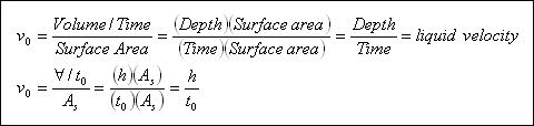
Let us now consider why the liquid-rise velocity is called an overflow rate and what its units are. The term overflow rate
is used since the water is flowing over the top of the tank into the weir system. It is sometimes referred to all the surface-loading rate because it has units of m3 / day . m2. The units are flow of water (m3 / day) being applied to a m2 of tank surface area per day, which is similar to loading rate. Recall from :
that the velocity of flow is equal to the flow rate divided by the area through which it flows, hence an overflow rate is
the same as a liquid velocity :
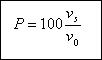
As long as vs is greater than v0, the particles will settle downward and be removed from the bottom
of the tank regardless of the depth. The percentage of particles removed, P, with a settling velocity of vs in
a sedimentation tank designed with an overflow rate of v0 is :
Problem 3...
The town of San Jose has an existing horizontal-flow sedimentation tank with an overflow rate of 17 m3 / day . m2, and it wishes to remove particles that have settling velocities of 0.1 mm / sec, 0.2 mm / sec and 1 mm /
sec. What percentage of removal should be expected for each particle in an ideal sedimentation tank ?
Problem 4...
Determine the surface area of a settling tank for the city of Urbana’s 0.5 m3 / sec design flow with design overflow rate of 32.5 m3 / day . m2. Compare this surface area with that which results from assuming
a typical overflow rate of 20 m3 / day . m2. Find the depth of the clarifier using detention time of 95 minutes.
Problem 5...
Design a sedimentation tank to treat 9.092 M1 per day of turbid water. Assume the detention period as 5 hours and
velocity of flow as 15 cm / minute.
4. Filtration...
The water leaving the sedimentation tank still contains floc particles. The settled water turbidity is generally in the
range from 1 to 10 TU with a typical value being 3 TU. In order to reduce this turbidity to 0.3 TU a filtration process is normally used. Water filtration is a process for separating suspended or colloidal impurities from water by passage through
a porous medium, usually a bed of sand or other medium. Water fills the pores (open pores) between the sand particles, and the impurities are left behind, either clogged in the open spaces or attached to the sand itself.
There are several methods of classifying filters. One way is to classify them according to the type of medium used such
as sand, coal, dual media (coal plus sand) or mixed media (coal, sand and garnet). Another common way to classify the
filters is by allowable loading rate. Loading rate is the flow rate of water applied per unit area of the filter. It is
the velocity of the water approaching the face of the filter :
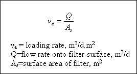
Based on loading rate, the filters are described as being slow sand filters, rapid sand filters, or high-rate sand filters.
Slow Filters...
Slow sand filters were first introduced in the 1800's. The water is applied to the sand at a loading rate of 2.9 to 7.6 m3 / day . m2. As the suspended or colloidal material is applied to the sand, the particles begin to collect in the top 75 mm and to clog the pore spaces. As the pores become clogged, water will no longer pass through the sand. At this point the top layer of sand is scraped off, cleaned and replaced. Slow sand filters require large areas of
land and are operator intensive. Basically, all the filters have the graded layers of gravel or other porous material (sand) through which water filters. An underdrain system is provided for collecting the filtered water. The slow sand filter is described below.
( i ) Adaptability : They are not preferred nowadays and rapid sand filters are replacing them. But still they are
economical and are more suited to warm climate where covers on the filters are not required to protect the filters from freezing. They are simpler in mechanism and operation and have a high bacterial efficiency as compared to rapid sand
filters.
( ii ) Bacterial removal efficiency : It is 99 %
( iii ) Turbidity limitation : The raw water from lake or river has turbidity up to 100 ppm. The slow sand filters cannot handle this load and even 50 ppm turbidity gives unsatisfactory results. The pre-sedimentation is the solution of the problem.
( iv ) Colour limitation : The raw coloured water over 30 ppm cannot be treated satisfactory.
( v ) Flexibility : A rapid change in rate is not permitted. They are not flexible to change in load.
( vi ) Cleaning : The cleaning of slow sand filter is done in 2 or 3 months depending upon the type of water and turbidity. Cleaning is done by scarping 5 cm top layer or a thick depth up to which the turbidity has penetrated.
Rapid Filters...
These filters have graded (layered) sand within the bed. The sand grain size distribution is selected to optimize the
passage of water while minimizing the passage of particulate matter. Rapid sand filters are cleaned in place by forcing
water backwards through the sand. This operation is called backwashing. The washwater flow rate is such that the sand is expanded and the filtered particles are removed from the bed. After back washing, the sand settles back into place.
There are different valves which are operated for different operations as described below :
( a ) Working of filter : Open valve 1 and allow the pre-coagulated and settled water to flow into the filter. This water percolates through various layers of graded sand and gravel and through underdrains it is collected in one main pipe, then
by opening valve 4 it flows into the clear water well.
( b ) Washing the filter : Close valve 1 to stop the flow of pre-settled water to filter and also close valve 4. Open valves 2 and 5 to allow the washwater from the overhead tank to rise up through the underdrains and layers of gravel and sand. The dirt etc is washed and the dirty water through the trough is carried away by the drains.
( c ) Running the filtered water to waste : This is done for a few minutes for conditioning the filter before it is put into service again. For this, close valves 2,4 and 5 and open valve 1 which will allow the coagulated and settled water to flow through the filter and underdrain and to run the waste water to the waste water drain by opening valve 3.
( d ) Resuming filtration : Now, keep valve 1 opened and close valve 3 and instead open valve 4 to allow the filtered water to go into filtered water reservoir.
The largest particles settle first, resulting in a fine sand layer on top and a coarse sand layer on the bottom. Rapid sand filters are the most common type of filter used in water treatment today. Traditionally, rapid sand filters have been designed to operate at a loading rate of 120 m3 / day . m2.
In general, the rapid filter characteristics are :
( i ) Adaptability : It is adopted in case of municipal water supply for colour and turbidity removal and for softening pre-treatment with lime and soda ash.
( ii ) Bacterial removal efficiency : It is 90-99% if properly operated.
( iii ) Turbidity limitation : The rapid sand filter is very efficient in handling a highly turbid water.
( iv ) Colour limitation : It is quite efficient in colour removal also.
( v ) Flexibility : The rate of filtration can be varied. But skilled operators are required for these filters to operate
the mechanical equipment.
Problem 6...
As part of Urbana new treatment plant, they are going to install rapid sand filters after their sedimentation tank. The design loading rate to the filter is 200 m3 / day . m2. How much filter surface area should be
provided for their design flow rate of 0.5 m3 / sec ? If the surface area per filter box is to be limited to 50 m2, how many filter boxes are required ?
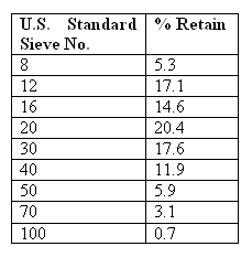
Grain Size Characteristics...
The size distribution or variation of a sample of granular material is determined by sieving the sample through a series
of standard sieves (screens). The grain size analysis begins by placing the sieve screens in ascending order with the
largest opening on the top and the smallest opening on the bottom. A sand sample is placed on the top sieve and the stack
is shaken for a prescribed amount of time. At the end of the shaking period, the mass of material retained on each sieve
is determined. The cumulative mass is recorded and converted into percentages by mass equal to or less than the size of separation of the overlying sieve (See table given below).
Filter Hydraulics...
During filtration the filter bed will become more and more clogged. As the filter clogs, the water level will rise above
the sand as it becomes harder to force water through the bed. Eventually, the water level rise to the point that the
filter bed must be cleaned. This point is called terminal head loss.
When water passes through filter and underdrain, it experiences frictional resistance and therefore a loss of head occurs. The top layer offers maximum resistance. This effect reduces greatly the rate of filtration and so a negative head more
than 1.5 m should not be allowed.
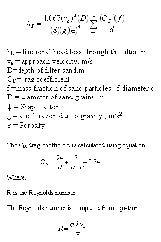
The loss of pressure (commonly termed head loss) through a clean stratified-sand filter with uniform porosity was described by Rose in the following form :
Problem 7...
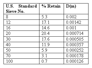
Estimate the clean filter had loss in Urbana’s proposed new sand filter using the sand described in the table given below. Use the following assumptions :
- Specific gravity of sand is 2.65
- The shape factor is 0.82
- The bed porosity is 0.45
- The water temperature is 10OC
- The depth of sand is 0.5 m
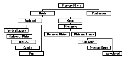
Pressure Filters...
Pressure filters are which the water enters at 2.8-4.2 kg / cm2 pressure, which is developed by pumps. Pressure filters have media (sand, anthracite, or calcite) and underdrains contained in a steel tank. Water is pumped through the filter under pressure and the media washed by reversing flow through the bed, flushing out the impurities. Pressure filters have the same general characteristic as rapid sand filters.
Pressure filters may be grouped as shown in the tree :
Horizontal Pressure Filter (HPF)...
The horizontal pressure filter system is applied for all filtration applications where the flow rate is more than 1 MGD
and less than 5 MGD. Single or dual media beds are available. A gravel support bed is used with all media combinations.
Vertical Pressure Filter (VPF)...
The vertical pressure filter system is applied for all filtration applications with flow rates of 2 MGD or less.
5. Disinfection...
Disinfection is used in water treatment to reduce pathogens (disease – producing microorganisms) to an acceptable level. Disinfection is not the same as sterilization. Sterilization implies the destruction of all living organisms. Drinking
water need not be sterile. Three categories of human enteric pathogens are normally of consequence: bacteria, viruses and amebic cysts. Purposeful disinfection must be capable of destroying all three. To be of practical service, such water disinfectants must possess the following properties :
1. They must destroy the kinds and numbers of pathogens that may be introduced into water within a practicable period
of time over an expected range in water temperature.
2. They must meet possible fluctuations in composition, concentration and condition of the waters or wastewaters to
be treated.
3. They must be neither toxic to humans and domestic animals nor unpalatable or otherwise objectionable in required concentrations.
4. They must be dispensable at reasonable cost and safe to store, transport, handle and apply.
5. Their strength or concentration in the treated water must be determined easily, quickly, and automatically.
6. They must persist within disinfected water in a sufficient concentration to provide reasonable residual protection against its possible recontamination before use or because this is not a normally attainable property-the disappearance of residuals must be a warning that recontamination may have taken place.
Disinfection Kinetics...
Under ideal conditions, when an exposed microorganism contains a single site vulnerable to a single unit of disinfectant,
the rate of die-off follows Chick’s law, which states that the number of organisms destroyed in a unit time is proportional to the number of organisms remaining :

This is a first-order reaction. Under real conditions the rate of kill may depart significantly from Chick’law. Increased rates of kill may occur because of a time lag in the disinfectant reaching vital centers in the cell. Decreased rates of
kill may occur because of declining concentrations of disinfectant in solution or poor distribution of organisms and disinfectant.
Chlorination...
Chlorine is the most common disinfecting chemical used. The term chlorination is often used synonymously with
disinfection. Chlorine may be used as the element (Cl2), as sodium hypochlorite (NaOCl), or as calcium hypochlorine [Ca(OCl)2].when chlorine is added to water, a mixture of hypochorous acid (HOCl) and
hydrochloric acid (HCl) is formed :
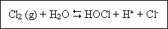
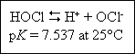
This reaction is pH dependent and essentially complete within a very few milliseconds. In dilute solution and at pH levels above 1.0, the equilibrium is displaced to the right and very little Cl2 exists in solution. Hypocholorous acid
is a weak acid and dissociates poorly at levels of pH below about 6. Between pH 6.0 and 8.5 there occurs a very sharp change from undissociated HOCl to almost complete dissociation :
Thus, chlorine exists predominantly as HOCl at pH levels between 4.0 and 6.0. Below pH 1.0, depending on the chloride concentration, the HOCl reverts back to Cl2. At 20OC, above about pH 7.5, and at 0OC,
above about pH 7.8, hypochlorite ions (OCl-) predominate. Hypochlorite ions exist almost exclusively at
levels of pH around 9 and above. Chlorine existing in the form of HOCl and / or OCl- is defined as free
available chlorine. Hypochlorite salts dissocuate in water to yield hypochlorite inos :
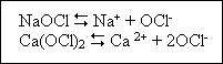
The hypochlorite ions establish equilibrium with hydrogen ions, again depending on pH. Thus, the same active chlorine
species and equilibrium are established in water regardless of whether elemental chlorine or hypochlorites are used. The significant difference is in the resultant pH and its influence on the relative amounts of HOCl and OCl-
existing at equilibrium. Elemental chlorine tends to decrease pH; each mg/l of chlorine added reduces the alkalinity by
up to 1.4 mg/l as CaCO3. Hypochlorites, on the other hand, always contain excess alkali to enhance their
stability and tend to raise the pH somewhat. We seek to maintain the design pH within a range of 6.5 to 7.5 to optimize disinfecting action.
Chlorine-Disinfecting Action...
Chlorine disinfection involves a very complex series of events and is influences by the kind and extent of reactions with chlorine-reactive materials (including nitrogen), temperature, pH, the viability of test organisms, and numerous other factors. Such factors greatly complicate attempts to determine the precise mode of action of chlorine on bacteria and
other microorganisms. Microorganism kill by disinfectant is assumed to follow the CT concept, that is, the product of disinfectant concentration (C) and time (T) yields a constant. CT is widely used as a criteria for CYST and virus disinfection. CT is an empirical expression for defining the nature of biological inactivation where :
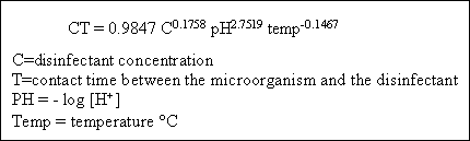
This relationship means that the required combination of concentration and time (CT) for reduction in Giardia cysts by
free chlorine can be estimated if the free chlorine concentration, pH and water temperature are known.
Chlorine / Ammonia Reactions...
The reactions of chlorine with ammonia are of great significance in water chlorination processes. When chlorine is added
to water that contains natural or added ammonia, the ammonia reacts with HOCl to form various chloramines, which like
HOCl, retain the oxidizing power of the chlorine. The reactions between chlorine and ammonia may be represented as
follows :
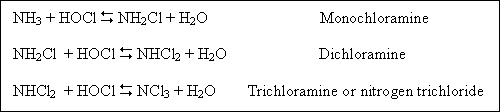
The distribution of the reaction products is governed by the rates of formation of monochloramine and dichloramine,
which are dependent upon pH, temperature, time, and initial Cl2 : NH3 ratio. In general, high Cl2 : NH3 ratios, low temperatures, and low pH levels favor dichloramine formation. Chlorine also reacts with organic nitrogenous materials, such as proteins and amino acids, to form organic chloramines complexes.
Chlorine that exists in water in chemical combination with ammonia or organic nitrogen compounds is defined as combined available chlorine.
Practices of Water Chlorination...
Evolution : Early water chlorination practices (variously termed “plain chlorination,” simple chlorination and marginal chlorination) were applied for the purpose of disinfection. Chlorine-ammonia treatment was soon thereafter introduced to limit the development of objectionable tastes and odors often associated with marginal chlorine disinfection. Subsequently, “super-chlorination” was developed for the additional purpose of destroying objectionable taste-and odor – producing substances often associated with chlorine – containing organic materials. The introduction of “breakpoint chlorination” and the recognition that chlorine residuals can exist in two distinct forms established contemporary water chlorination as one of two types.
Combined residual chlorination : Combined residual chlorination practice involves the application of chlorine to
water in order to produce, with natural or added ammonia, combined available chlorine residual, and to maintain that
residual through part or all of a water treatment plant or distribution system. Combined available chlorine forms have
lower oxidation potentials than free available chlorineforms and, therefore, are less effective as oxidants. Moreover,
they are also less effective disinfectants. In fact, about 25 times as much combined available residual chlorine is
necessary to obtain equivalent bacterial kills under the same conditions of pH, temperature, and contact time. And about
100 times longer contact is required to obtain equivalent bacterial kills under the same conditions and for equal amounts
of combined and free available chlorine residuals.
When a combined available chlorine residual is desired, the characteristics of the water will determine how it can be accomplished :
1. If the water contains sufficient ammonia to produce with added chlorine a combined available chlorine residual of
the desired magnitude, the application of chlorine alone suffices.
2. If the water contains too little or no ammonia, the addition of both chlorine and ammonia is required.
3. If the water has an existing free available chlorine residual, the addition of ammonia will convert the residual
to combined available residual chlorine. A combined available chlorine residual contain little or no free available
chlorine.
The practice of combined residual chlorination is especially applicable after filtration (posttreatment) for controlling certain algae and bacterial growths and for providing and maintaining a stable residual throughout the system to the point
of consumer use.
Although combined chlorine residual is not a good disinfectant, it has an advantage over free chlorine residual in that it
is reduced more slowly and therefore persists for a longer time in the distribution system. Thus, it is useful as an indicator of major contamination. Water plant personnel routinely monitor the chlorine level in the distribution system.
The presence of available chlorine either combined or free indicates that no major contamination has occurred. If major contamination does take place, the combined chlorine residual will be depleted, albeit at a slow rate. This depletion
serves as warning that contamination may have taken place.
Because of its relatively poor disinfecting power, combined residual chlorination is often preceded by free residual chlorination to ensure the production of potable water.
Free residual chlorination : Free residual chlorination practice involves the application of chlorine to water to produce, either directly or through the destruction of ammonia, a free available chlorine residual and to maintain that residual through part or all of a water treatment plant or distribution system. Free available chlorine forms have higher oxidation potentials than combined available chlorine forms and therefore are more effective as oxidants. Moreover, as already noted, they are also the most effective disinfectants.
When free available chlorine residual is desired, the characteristics of the water will determine how it can be
accomplished :
1. If the water contains no ammonia, the application of chlorine will yield a free residual.
2. If the water does contain ammonia that results in the formation of a combined available chlorine residual,
it must be destroyed by applying an excess of chlorine.
With molar Cl2 : NH3, concentrations up to 1:1 monochloramine and dichloramine will be formed. The relative amounts of each depend on pH and other factors. Chloramine residuals generally reach a maximum at equimolar concentrations of chlorine and ammonia. Further increase in the Cl2 : NH3 ratio result in the
oxidation of ammonia and reduction of chlorine. These oxidation/reduction reactions are essentially complete when two
moles of chlorine have been added for each mole of ammonia present. Sufficient time must be provided to allow the reaction
to go to completion. Chloramine residuals decline to a minimum value, the breakpoint, when the molar Cl2 : NH3 ratio is about 2 : 1. At this point, oxidation/reduction reactions are essentially complete.
6. Aeration...
The aeration can be accomplished by various means. It may be done by spraying the air through nozzles under a pressure of about 1.05-1.40 kg / cm2 or it can be done by allowing the water to flow over cascades or series of steps or weirs. It can also be done by blowing compressed air through diffuser porous plates at the bottom of the settling tanks.
The water due to aeration absorbs oxygen and allows carbon dioxide gas to escape. The aeration improves the taste and
odour. It also removes the excess of iron from ground waters. Soluble iron is readily oxidized by the following
reaction :
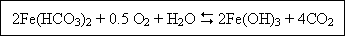
Aeration also removes corrosiveness to some extent. Too much aeration should be avoided. For the waters which are drawn
from great depths and are pure sufficiently and do not require filtration etc, the aeration is the only process adopted
to further improve the quality.
Water Treatment System...
The raw (untreated) surface water enters the plant via pumps. Usually screening has taken place prior to pumping. During mixing, chemicals called coagulants are added and rapidly dispersed through the water. The chemical reacts with the desired impurities and forms precipitants (flocs) that are slowly brought into contact with one another during flocculation. The objective of flocculation is to allow the flocs to collide and grow to a settleable size. The particles are removed by gravity (sedimentation). This is done to minimize the amount of solids that are applied to the filters. For treatment works with a high – quality raw water, it may be possible to omit sedimentation and perhaps flocculation. This modification is called direct filtration. Filtration is the final polishing (removal) of particles. During filtration the water is passed through sand or similar media to screen out the fine particles that will not settle. Disinfection is the addition of chemicals (usually chlorine) to kill or reduce the number of pathogenic organisms. Disinfection of the raw water is neither economical nor efficient. The color and turbidity consume the disinfectant thus requiring the use if excessive amounts of chemical. In addition, the presence of turbidity may shield the pathogens from the action of the disinfectant and thereby prevent efficient destruction. Storage may be provided at the plant or located within the community to meet peak demands
and to allow the plant to operate on a uniform schedule. The high – lift pumps provide sufficient pressure to convey the water to its ultimate destination. The precipitated chemicals, original turbidity, and suspended materials are removed from the sedimentation basins and form the filters. This sludge must be disposed of properly.
