Mechanical Aeration...


General Considerations...

Mechanical aeration is performed by rotating devices which are slightly submerged into the water and thereby effecct spreading of the water above the water surface. This action at the same time enforces a spirally shaped flow of the water within the tank, the pattern of which depends on the geometry of the aeration device and the tank. The exchange of gases by the described action of mechanical aerators is achieved by several mechanism :

( 1 ) By spreading of the water in the form of droplets and / or water films above the water surface a large interfacial area is created.

( 2 ) By reentering of the spread droplets and films of water into the bulk of the tank content the gases absorbed at their surfaces are mixed with the bulk of the water. Furthermore bubbles are entrained when the spread water submerges into the tank content, an effect similar to that observed in weir aeration, however less pronounced due to the low height of fall.

( 3 ) An entrainement of bubbles into the water is achieved by the rotating device itself. At certain points of the device the velocity of the water is great enough as to locally produce a partical vacuum by which the entrainement is caused. Some devices are especially equipped to promote this additional effect of gas transfer.

( 4 ) The pattern of flow in the tank induced by the aerator furnishes a steady renewal of the water surface of the tank, assisting in gas exchange. Moreover the spiral like flow pattern is frequently of a velocity great enough to carry the entrained bubbles downwards, which leads to a longer time of contact between bubbles and water. High streaming velocities of the water in the same direction as the peripheral motion of the aerating device are to be avoided. Thereby the velocity difference between water and aerator decreases, may eventually approach zero, and the above major mechanisms of gas transfer are minimized.

Thus it is seen, that a variety of mechanisms cause the exchange of gases in mechanical aeration. The alternative term of " surface aeration " refers only to the mechanisms mentioned under ( 1 ) and partially under ( 2 ). The greater the share of the total gas transfer by these mechanisms is, the more is the term " surface aeration " justified. A quantitative measure for this effect may be the flow of water ( m 3 / s )spread by the aerators by its " pumping action ". The other mechanisms causing gas transfer are strongly dependent on the size and shape of the aeration tank which mainly determine the flow pattern.


Mechanical aeration is primarily used for oxygenation of the mixed liquor in activated sludge treatment. Comparing mechanical aeration with air diffusion, some of the more obvious advantages of mechanical aerators are the elimination of several appurtenances of the diffused air system such as piping, bracnhing of pipes, valves, blowers or fans, air filters etc. Moreover the mechanical aerator is also generally more maintenance free and does not need the high degree of attention that is required for cleaning of the diffusers. These advantages have led to almost an explosion of marketed types of mechanical aerators, the end of which seems not yet to be within sight. This development has been promoted by the fact, that mechanical aerators can easily be float mounted and thus conveniently be applied in larger tanks or for aeration of lagoons or surface waters.

Basically, the types of mechanical aerators may be differentiated as follows ;

( 1 ) Rotor aerators ( formerly referred to as " brushes " ), consisting of a horizontal revolving shaft with combs, blades or angles attached to it which are slightly dipping into the water.
( 2 ) Cones, impellers or turbines revolving round a vertical shaft. The cones may be further subdivided into the following types ;
( a ) Plate types ; discharging the water in radial direction at the tank surface at high velocity which leads to a peripheral hydraulic jump. Both effects cause a rapid renewal of the air - water interface and partially also air entrainement.
( b ) Updraft types ; actually acting like a pump, discharging large quantities of water at the surface at relativeley low heads.
( c ) Downdraft types ; a unit where oxygen is supplied by air selfinduced from a negative head produced by the rotating element. Due to this entrainement of air, being the prime mechanism of gas transfer, the downdraft types are no surface aerators.

The oxygen transfer efficiency of mechanical aerators is generally stated in g of oxygen transferred per aerator per second, ( or kg O 2 / h ), being equivalent to the oxygenation capacity ( OC ). Prime factors influencing the oxygenation capacity are the size of the aerator, the depth of submergence, the speed of rotation. Concerning the size, the diameter gives sufficient information for cone - type aerators, mentioned under ( 2 ), whereas the oxygenation capacity for rotors is generally related to their diameter and a rotor length of 1 m. Increasing these controlling parameters will generally increase the OC, but will vary the oxygenation efficiency ( OE, mg O 2 / J or generally kg O 2 / kWh ) in such fashion as to provide optimum conditions at a certain magnitude of rotational speed and submergence as is qualitatively shown in figure given below. At magnitudes of the controlling parameters below the optimum values, the OC generally increasas with increasing the size of the aeration device, expressed by its diameter ( D C ), the depth of immersion ( D I ), and its peripheral speed ( V P ). Generally, this increase may be approximated by the following relations concerning ;

( a ) The size of the aerator ; OC is a function of D C 2
( b ) The depth of immersion ; OC is a function of D I
( c ) The peripheral speed ; OC is a function of V P n ( with 2.5 < n < 3.0 )


As already has been mentioned, also the pattern of flow and its velocity are of significant influence on the OC. Both parameters are primarily modified by the size and the geometry of the tank, keeping the size of the cone, its rotational speed and depth of immersion constant. Quantitative measures for these influences are the velocity difference between water and the aerator periphery and the ratios of aerator diameter D C over the tank width w ( D C / w ) and over the tank depth d ( D C / d ). Applying well shaped aeration tanks, the size then will have a great influence on the OC achieved with a surface unit. Generally speaking, the larger the tank is, the smaller are the velocities of the induced spiral flow and the less pronounced are the transfer mechanisms mentioned under point 4.

A quantitative measure for this influence is the amount of energy dissipated per unit tank volume E G ( W / m 3 ) which will be seen to be of significant influence on the OE. Concerning the influence of hydrophobic and surface active matter on the OC of mechanical aerators it may be stated, that the turbulence in the region of the aerrator is generally largeenough to prevent reformation of a layer of such substances at the produced air - water interfaces. Thus the positive effects of surface active agents on gas transfer will prevail and cause an increase of the OC with increasing content of surfactants. On the other hand, the effect of the entrained air bubbles on gas exchange will generally be lowered by the presence of surfactants, as was evident for air diffusion systems. The sum of both effects leads generally to a much less pronounced decrease of the rate of gas transfer by surface active matter than in bubble aeration ; frequently such substances will even increase the OC of a surface aerator.

Rotor Aerators...

Types of Rotor Aerators and Their Arrangement...

The predecessor of the rotor aerators are the " Haworth " or " Sheffield " paddles ( see figure given below ), developed as early as 1916 in England, which where used in combination with snakewise arranged channels of some 1 m of width and 1 to 1.5 m depth. By rotation of the paddles of 2 m of diameter some transfer of oxygen was achieved, but mainly the induced streaming velocity of some 0.5 m / s provided aeration of the mixed liquor.


At present, basically 2 types of rotors are available ;

( 1 ) The cage - rotor, consisting of two steel discs attached to the central shaft at both ends with T - shaped bars are attached to the discs ( hence being placed parallel to the shaft ). To each of the 12 T - bars a series of short steel plates each about 0.15 m long and 0.05 m wide are bolted at right angles, spaced at about 0.05 m clear distance. The overall diameter amounts to 0.70 m, the maximum length is some 3.0 to 5.0 m.

( 2 ) The plate rotor consists of a shaft onto which short lengths of steel plates are clamped in a star - like manner. The total diameter is some 0.5 m, the maximum length about 2.5 m. A recent development of the plate rotor is the so - called mammoth rotor. The constructional principle is the same, however the total diameter is increased up to 1.0 m, which allows total lengths of some 9.0 m.


For more information especially visit these web - sites...

Usfilter Spaansbabcock Giantexplorer
Aireo2 Biwater EPA

Rotors are applied in connection with two types of tanks ;

( 1 ) A tank of rectangular or rounded cross - section with the brushes placed along one side of the tank length. The rotors then induce a spiral flow which is rectangular to the displacement velocity of the mixed liquor through the tank. Fot this type of tank generally plate rotors or mammoth rotors are applied although cage - rotors have been used also. To achieve thorough mixing all over the cross - section guide baffles are frequently required which force the water velocity induced at the tank surface into the deeper parts of the tank.


Rectangular tanks are additionaly equipped suction baffles under the rotor, which assist in achieving a good mixing also with this type of cross - section. With plate rotors the cross - section is generally square, whereas with mammoth rotors the width may be increased to twice the depth without serious decrease of proper mixing conditions. The rotors may be covered with easily removable splash - guards.


( 2 ) A long circuit - like tank of rectangular or trapezoidal cross - section. One or more rotors are arranged across the circuit channel and induce a longitudinal velocity great enough for proper mixing of the mixed liquor. Classical examples of this types of tank are the " Haworth " channel and the oxidation ditch. For this type of tank the cage rotor and the mammoth rotor are primarly applied. In order to achieve proper mixing all over the cross - sectional area the depth of either tank type has to be limited to some 3.50 m. The ditch - type tank, when operated with cage - rotors, should not exceed a depth of 1.50 to 1.60 m.


Channel - like tank with mammoth - rotors...


Oxidation ditch with cage rotor...

From My Photo Collection...

Important notice : 1994 - 2006 © Toprak Home Page... You may use these pics at your web - site... But, first of all, before downloading them, you must inform me via e - mail by clicking on the one of the buttons located below... After getting the permit, you must locate the "TOPRAK HOME PAGE"s banner shown below into your web - site, and you must create a link via this banner to the "TOPRAK HOME PAGE"...


Factors Influencing the Rate and Efficiency of Oxygen Transfer...

The main mechanisms of gas transfer by rotor aeration are ;

- Whipping of air bubbles into the water by the blades of the rotor
- Spreading of the water in the form of droplets over the water surface in front of the rotor
- Inducing a circular or longitudinal streaming velocity possibly guided by baffles, which renews the water surface and submerges the entrained air bubbles

The main factors which determine the OC achieved by these mechanisms are the peripheral speed of the rotor v P ( m / s ), the depth of submergence of the blades of the rotor d I ( m ). Generally, the OC per m of rotor length ( OC L in g O 2 / s . m of rotor length ) increases in proportion to the depth of immersion d I and to some power of the peripheral speed v P ;

OC L = ( K R ) ( v P BETA ) ( d I )

where ; K R : a constant depending on the specific rotor construction and the tank geometry and BETA : exponent.

For a tank of square cross - sectional area ( 3.0 m width and 3.0 m depth ) equipped with pressure and suction baffles, for instance, the above constants for a plate type rotor of 0.52 m total diameter were found to be K R = 1.33 and BETA = 2.60 at depths of immersion of 0.04 <= d I <= 0.14 m and peripheral velocities of 1.80 <= v P <= 2.40 m / s. From further investigations it may be concluded that especially K R is strongly dependent on the specific conditions of rotor and tank construction, whereas much less variation of the exponent BETA is to be expected. Since the gross power required generally increases in proportion to the depth of immersion d I and to the second power of the peripheral speed v P 2 , it is evident from the equation given above that variation of the depth of immersion d I will not alter the OE significantly, whereas the difference of the exponents of v P referring to OC L and the gross power indicates, that the OE will increase with increasing v P . This would call for very high numbers of revolution of the rotor. In practical operation, however, an upper limit is set due to the fact that hydrophic and surface active matter reduce the spiral velocity of the tank at high rotational speeds. Frequently the spiral flow is confined to the upper part of the tank, the constant of which renders into a dispersion of fine bubbles in the water, rotating above the water of the lower part of the tank. This effect may be strongly reduced by the baffles, but nevertheless an " optimum " peripheral speed can be established in terms of maximum OE. An example is given in figure shown below, indicating v P = 2.40 m / s to be optimum for a square tank.


The rotational speed nowedays applied is generally set by the manufacturers. Plate rotors with a total diameter of 0.50 m are mostly designed for 2.0 rps ( 120 rpm ), giving v P = 3.14 m / s, the depth of immersion being varied from 0.05 to 0.15 m ; cage rotors for 1.25 to 1.33 rps ( 75 to 80 rpm ), with 2.75 <= v P <= 2.93 and a range for d I of some 0.10 to 0.20 m ; whereas large rotors of 1 m of diameter are manufactured for 0.88 rps ( 53 rpm ) corresponding to v P = 2.77 m / s and for 1.20 rps ( 72 rpm ) which is equivalent to v P = 3.77 m / s, with a depth variation from 0.10 to 0.30 m. Within the variations caused by the size and geometry of the tank the following empirical equations are given to estimate the OC per m length of rotor.

( a ) Plate rotor : OC L = - 0.25 + ( 13.7 ) ( d I ) [ kg O 2 / h . m ]

( b ) Cage rotor : OC L = - 2.2 + ( 32.8 ) ( d I ) [ kg O 2 / h . m ]

( c ) Large rotor : OC L = - 0.4 + ( 42.0 ) ( d I ) [ kg O 2 / h . m ]

Example...

Estimate the total length of ( a ) plate and ( b ) mammoth rotors to supply the oxygen requirement of an activated sludge plant, which amounts to 45 g O 2 / s as daily average. Select the depth of immersion in order to meet the expected hourly variations of the oxygen demand ranging from 0.70 to 1.30 of the daily average. Assume C S = 10 g / m 3 , 2 g O 2 / m 3 to be maintained in the aeration tank and ALPHA = 1.0. Estimate the average power dissipation E G ( W / m 3 ), assuming an average OE of 0.55 mg O 2 / J ( 2 kg O 2 / kWh ) and a total tank volume of 1,000 m 3 .

( a ) Plate rotor :

The maximum oxygen demand is ( 1.3 ) ( 45 ) = 58.5 g O 2 / s for which d I is chosen at maximum d I = 0.15 m. At operational conditions the OC L - OP of the rotor is ;

OC L - OP = [ ( OC L ) ( ALPHA ) ( C S - C ) ] / ( C S ) = [ ( OC L ) ( 1.0 ) ( 10 - 2 ) ] / ( 10 ) = ( 0.8 ) ( OC L )

The total rotor length L R ;

( 58.5 ) = ( 0.8 ) ( OC L ) ( L R ) = ( 0.8 ) ( L R ) [ - 0.070 + ( 3.8 ) ( 0.15 ) ]

L R = 147 m

With the maximum rotor length of 2.5 m this would require ( 147 ) / ( 2.5 ) = 58.8, hence 59 rotors, each 2.5 m long. Similarly, the depth of immersion at minimum oxygen demand of ( 0.7 ) ( 45 ) = 31.5 g O 2 / s may be estimated from ;

( 31.5 ) = ( 0.8 ) ( 147 ) [ - 0.070 + ( 3.8 ) ( d I ) ]

d I = 0.089 m

Since the construction length including bearings of the rotor is some 3.0 m, the 59 rotors require a tank length of ( 59 ) ( 3.0 ) = 177 m, which corresponds to a cross - sectional area of ( 1,000 ) / ( 177 ) = 5.6 m 2 .

Note from the " TOPRAK HOME PAGE "

It should be better to have 60 rotors, as twin number, for an easy construction and installation. In addition, the total length should be 180 m.

( b ) Mammoth rotor :

For the peak oxygen demand of 58.5 g O 2 / s a depth of immersion of d I = 0.30 is chosen. OC L amounts to 2.9 g O 2 / s . m. Hence ;

( 2.9 ) ( 1.0 ) [ ( 10 - 2 ) / ( 10 ) ] ( L R ) = 58.5

L R = 25.2 m

To estimate d I for the minimum oxygen demand ;

( 31.5 ) = ( 0.8 ) ( 25.2 ) [ - 0.11 + ( 11.7 ) ( d I ) ]

d I = 0.14 m

The design would include 6 mammoth rotors of 4.5 m length each, arranged in a channel - like tank with a total width of ( 2 ) ( 4.5 + 1.0 ) = 11.0 m. Taking a depth of 2.5 m the length of the tank would be ( 1,000 ) / [ ( 11.0 ) ( 2.5 ) ] = 37 m. The average power dissipation, based on 0.55 mg O 2 / J and 45 g O 2 / s amounts to ( 45 ) / ( 0.55 x 10 - 3 ) = 82,000 J / s = 82 kw.

Cone Aeration...

Contrary to rotors cones are mounted on a vertical shaft. Therefore, they are generally arranged within a tank of square or round horizontal cross - section. Several tank units may be combined to a large tank. This arrangement induces two spiral motions overlapping each other to a complex pattern of flow. The first type is caused by the " pumping " and / or radial discharge action of the cone, producing an upward flow in the tank center and a downward flow near the tank walls ( vertical spiral flow ). The second type of motion is a slow rotation of the total tank content induced by the rotation of the impeller ( horizontal spiral flow ). The vertical spiral flow significantly controls the rate of gas transfer, whereas an increase of the horizontal spiral flow decreases the velocity difference between water and cone periphery and thus decreases the OC and OE. Frequently, the tank is equipped with baffles in order to minimize the horizontal spiral flow. Cone aeration is also applied in connection with a special type of oxidation ditch ( type " carrousel " ). The basic principle is also a round or square tank, but to one side two long channels are connected, which provide the large tank volume required for oxidation ditches. This, obviously, then leads to a longitudinal flow pattern rather than to a spiral one. In other words ; the horizontal spiral flow induced by the cone is transformed to a longitudinal flow by means of the middle wall extending up to the cone periphery. Finally, cone aeration is extensively used in aerated lagoons and for reaeration of surface waters. For this purpose the aerators are frequently float mounted, whereas for the other types of application bridge mounting is the design of preference, although some of the cone types used in large tanks are float mounted. The tank dimensions for optimum oxygen transfer and operation depend primarily on the size of the cones, ranging from some 0.40 m to 4.50 m, and secondly on the type of cone.

Plate Aerators...

The best known plate aerator is the " Vortair - Cone " which consists of a circular flat plate with 20 to 30 vertical blades attached at the periphery of the plate. The angle of the plates with the radius is adjustable from 0 O to 25 O . Openings behind the blades facilitate entrainement of air.


The " Vortair - Cone " is manufactured in 16 different sizes ranging from 0.40 to 4.50 m in diameter. The cone uses a standard motor and gear drive unit. The gross power input varies within the above range of sizes from 0.75 to 75 kW. As already mentioned, the oxygen transfer is basically achieved by two mechanisms. At rotation of the cone slightly below the water level, the water is radially discharged which leads to a peripheral hydraulic jump. At optimum rotational speed the top plate is clear of water and air is entrained through the openings due to the low pressure behind each of the blades. This second effect accounts for some 10 % of the OC.


Although the " Vortair - Cone " has originally been developed for aeration of ponds and lagoons, it has sucessfully been applied in conventional activated sludge treatment at tank depths 2.0 to 3.5 m depending on the cone size. At greater depths the OC generally decreases.

Updraft Aerators...

The updraft type is the most common cone aerator. The variety of updraft types marketed requires a further subdivision into types working according to somewhat different principles ; although the common principle is a pumping action, there is a certain difference in the way of discharging the water ; either the water is issued in the form of large jets onto the water surface at low head ( jet aerators ) or it is sprayed. In the first case the cone somewhat resembles an impeller of a centrifugal pump, in the second case a vane - type pump is submerged issuing the water at an orifice in an exposure pattern formed by the diffuser. The jet aerators apply open and closed impeller cones. The pumping action of the closed units is somewhat superior but they are more likely to clogg. Finally, the updraft may be guided by draft tubes which permits greater tank depths to be applied. The following aerators will be discussed ;

( a ) Simcar - cone : An open impeller ( jet aerator without draft tube ).
( b ) Gyrox - cone : Open and closed impeller ( jet aerator without draft tube).
( c ) Simplex - cone : 3 closed types of impellers ( jet aerators with draft tube), partially combined with plates peripherally mounted on the impeller to produce a hydraulic jump.
( d ) BSK - turbine : A open and closed impeller unit ( jet aerator without draft tube ).
( e ) Hamburg - rotor : A rotating draft tube with 6 to 10 radially mounted discharge tubes ( jets ) and plates for inducing a peripheral hydraulic jump.
( f ) Aqua - lator : A closed spray aerator.

Simcar - Cones...

The Simcar - cone consists of a cone - shaped disc with square bar blades radiating outwards from almost the center. At the periphery the blades are horizontal. The depth of submergence may be varied from the point when the horizontal blades just touch the water surface ( minimum d I ) up to the 1.4 times the height of the blades. Frequently, the depth of submergence of cones is referred to by " freeboard ", ( f B ) which is defined by ;

+ f B = - d I

The cone is manufactured in the size range from 0.4 m to 3.6 m of diameter. The OC ranges from some 0.3 to 50 g O 2 / s ( 1.0 to 180 kg O 2 / h ), respectively. The optimum dimensions of a square tank are established at a ratio of width over depth of 2 to 4 with a maximum depth of 5.0 m.

Gyrox - Cones...

Gyrox - cones may be looked at as a further development of the " Vortiair - Cone " ; the open gyrox - cone ( type SE ) consistsof a circular plate onto which curved impeller vanes are attached. Openings in the top plate behind the vanes increase the entrainement of air. The closed type of the gyrox - cone is based on the same construction. A part of the vanes is, however, covered by a truncated cone, which extends at the lower end into a short draft tube. The closed construction provides a somewhat more intensive circulation of the tank content, requires, however, primary sedimentation to prevent clogging. Like many of the cones with curved vanes, the gyrox - cones may be operated at both directions of rotation. The normal rotation in direction of the concavity of the vanes is frequently referred to as " dragging ", whereas the opposite direction, when the convex parts of the vanes " bite " or " push " into the water, is generally called the " opposite ", " biting ", or " pushing direction ". The latter obviously achieves a greater OC. The range of cone sizes, the corresponding average OC and the optimum tank dimensions are stated in table given below.

Simplex - Cones...

The basic type ( type HL ) consists of an open - ended conical shell formed out of steel plate, to the inner face of which a number of specially shaped blades are attached. The conical shell extends at the lower end into a ring, which covers the stationary draft tube of the tank. On the top of the vanes an annular ring is welded. Into this ring a number of short stays are fitted, which support the cone from the driving ring attached to the gear head. The type simplex - S is essentially like the HL - type but a number of steel blades are fixed to the outer part of the conical shell additionally. Thereby, not only the pumping action of the inner construction but also the turbulence of the water surface induced by the outer ribs assists in transferring oxygen. Obviously, the OC of the S - type is superior to that of the HL - type. A further increase of the OC is achieved by the SL - type, which is mainly a completely closed impeller, discharging water jets at low head. The channels of the impeller are large to prevent clogging. The E - type is based again on the HL - type, however, a circular plate of a diameter greater than the cone covers the blades. This plate disintegrates the discharged water jets to some degree, creating a larger interfacial area between air and water. The simplex types are manufactured in sizes from 0.6 to 3.0 m of diameter. They may be arranged to adjust the freeboard or fixed. The range of variation of the depth of submergence is limited by stationary draft tube. Due to the action of the draft tube tanks equipped with simplex - cones are generally deeper than with other cones. The optimum ratio of width to depth for square tanks ranges from 2 to 3. With very shallow tanks or for aeration of lagoons or surface waters the stationary draft tube may be omitted.

BSK - Turbines...

The BSK - turbine is a cone - like impeller made out of glasfiber reinforced polyester. With the open type, named " Gigant ", the impeller channels are formed by open T - like beams situated at the bottom side of the cone, whereas with the closed type named " Favorit ", the channels are covered giving rise to an increased pumping action of the impeller. The top plate of the closed type contains holes for entrainement of air. Both turbines are operated in the normal directions of rotation as well as in the " biting " direction for achieving higher OCs. The open type is produced in sizes from 0.75 to 2.00 m of diameter with a range of OC from some 0.3 to 28 g O 2 / s ( 1 to 100 kg O 2 / h ), the closed type from 0.50 to 3.15 m and 0.3 to 100 g O 2 / s ( 1 to 370 kg O 2 / h ), respectively. For optimum oxygen transfer the ratio of width to depth of square tanks should be in the range of 2.5 to 4.5. At greater depths a cone situated at the tank bottom under the aerator is installed to provide proper circulation of the water content ; at smaller depths baffles are designed near the side walls to brake the horizontal circular motion of the tank content.

Hamburg - Rotor...

The Hamburg - rotor consists of a short rotating draft tube with a number of radially mounted discharge tubes, leaving the central tube at a slight angle upwards. Into the angle under each discharge tube a triangular steel plate is welded. In its normal position the lower edge of the discharge tubes is at the height of the water level. When rotating, the discharge tubes jet the water over the tank surface thus producing an updraft which induces a spiral motion of the tank content. The triangular plates and the outer side of the tubes cause - like the plates of the " vortair - cone " a peripheral hydraulic jump. The Hamburg - rotor is manufactured in size from 1.0 to 3.6 m total diameter, with OCs from 1.7 to 70 g O 2 / s ( 6 to 250 kg O 2 / h ). For optimum oxygenation in square tanks the ratio of width to depth to rotor diameter is advised to range from 3 : 1 : 0.6 to 4 : 1 : 0.67.

For more information especially visit these web - sites...

Usfilter Spaansbabcock Giantexplorer

Aqua - Lator...

Aqua - lator consists of a float mounted high speed impeller which sucks the water through a short draft tube and sprays it through a discharge cone over the tank surface. The circular float unit is made out of glasfiber inforced polyester, filled with plastic foam. The aqua - lator is available on various sizes up to some 3.50 m diameter of the total unit with OCs from about 2 to 25 g O 2 / s ( 7 to 90 kg O 2 / h ). Although preferably used for the aeration of lagoons, ponds and surface waters, the aqua - lator may also be applied in large activated sludge tanks. Due to the intense updraft the minimum depth of lagoons and ponds is 2 to 3 m to prevent erosion of the bottom, whereas the minimum depth is already reached at 3.5 to 4.2 m, depending on the size of the turbine. To the lower end of the draft tube a flat cone may be attached to prevent erosion by inducing a vertical input velocity. The depths then can be reduced to 0.8 to 1.2 m, respectively.

From My Photo Collection...

Important notice : 1994 - 2006 © Toprak Home Page... You may use these pics at your web - site... But, first of all, before downloading them, you must inform me via e - mail by clicking on the one of the buttons located below... After getting the permit, you must locate the "TOPRAK HOME PAGE"s banner shown below into your web - site, and you must create a link via this banner to the "TOPRAK HOME PAGE"...


Downdraft Aerators...

The common principle of all downdraft aerators is a turbine placed at or near the bottom of a square or round tank. The high speed turbine induces a downdraft followed by a circular motion of the tank content in a direction opposite to that of the updraft types. The high water velocities near the impeller produce a partial vacuum entraining air through the hollow drive shaft extending into the air. A small additional effect of gas transfer is achieved by the constant renewal of the water surface. Most of the dissipated energy is used, however, for creating turbulence, not of air - water interfaces, giving rise to low OCs and OEs. Since moreover the OC cannot be varied in a simple manner under operational conditions, it is obvious that downdraft aerators have more and more been displaced by updraft types.

Factors Influencing the Rate and Efficiency of Oxygen Transfer...

Referring to the discussed mechanisms of oxygen transfer by mechanical aeration, it is evident that the oxygenation capacity of cones is primarly determined by the flow pumped by the aerator and by the size of the jets or droplets spread onto the surface. The flow is strongly influenced by the size of the cone or its diameter, D C , the rotational speed or peripheral speed v P , its direction, and the depth of submergence d I or freeboard. These factors and furthermore the construction of the cone itself determine the air - liquid interface of the discharged water. The additional effects of gas transfer by air entrainement, previously discussed, are basically determined by the tank size ; the smaller the tank is, the greater are the spiral velociities and the more significant are these " secondary " effects. In an infinitely large tank volume ( pond, lagoon, surface water ) these effects will almost approach zero. Hence it is reasonable to relate the OC and OE to the power dissipation per unit volume EPSILON G ( W / m 3 ). Qualitatively, a greater EPSILON G will yield a higher OC and a greater OE. The power dissipation again, is determined by the before mentioned factors of D C , v P , d I and direction of rotation. The forementioned considerations will be discussed in the following by means of a few examples referring to updraft aerators. The influence of the cone diameter D C , the peripheral speed v P and the depth of immersion on the OC has been shown to follow relationship.

OC = ( k C ) [ 1 + ( k I ) ( d I ) ] ( D C n ) ( v P m ) ( g O 2 / s )

where ; k C : a constant dependent on the shape of the tank and the construction of the cone, k I : a constant to account for the depth of immersion of the cone d I , n : a constant signifying the influence of the cone diameter and m : a constant signifying the influence of the peripheral speed.

For the BSK - turbine and the Simcar - cone the constants have been found in tank volumes of 1,200 m 3 ( BSK ) and from 110 to 600 m 3 ( Simcar ) as follows ;

Turbine / Cone D C k C k I n m
BSK 2.0 0.028 2.9 2 3
BSK 3.0 0.028 3.3 2 3
Simcar 2.3 0.015 3.1 2 3
Simcar 3.6 0.015 1.9 2 3

The above information is of limited value, however, since especially the constant k C is strongly dependent on the chosen condition of tank size and shape and the type of the aerator. The linear influence of the depth of immersion and peripheral speed on the OC is shown in figure given below, respectively.

- For the Simplex HL - cone ( a ), D C = 1.52 m, V = 120 m 3
- For the Simcar - cone ( b ), D C = 2.29 m, V = 115 m 3
- For the Vortair - cone ( c ), D C = 1.04 m, V = 135 m 3

For the Vortair - cone ;

Angle of plates rpm v P ( m / s )
Radially 83 4.5
25 O 107 5.8
25 O 87 4.7
Radially 65 3.5
25 O 65 3.5

For both updraft types the linear influence is seen, whereas the plate type ( Vortair ) has a pronounced optimum d I . Variation of d I and v P , therefore, is an effective means for controlling the OC. Generally, the OC of all updraft types may be adjusted by variation of the depth if immersion over a range from about 40 % to 100 % of the maximum capacity. Concerning the peripheral speed , cones are operated from about 2 to 7 m / s, the optimum peripheral speed with regard to the OE ranging between 3.5 to 5.0 m / s. Within these ranges the greater velocities refer to smaller cones and vice versa. Changing v P by means of motors with pole changing windings ( e.g. doubling of rotational speed ) would allow to reduce the OC from 100 % to 12.5 % of the maximum capacity. In practice, however, a gradual control is required to meet the variation of the oxygen demand. This is most effectively attained by variation of the depth of immersion of the cone. On the other hand, an alteration of the rotational speed also influences the " secondary effects " of surface aeration. Hence the range of control is generally less than would be expected from the above consideration. By combining both control mechanisms ( d I and v P ) the OC may commonly be varied from about 15 % to 100 % of the maximum capacity. As already mentioned, the influence of the tank size may be accounted for by relating power dissipation per unit volume to the OC. Since the power requirement of a mixing device generally increases with the second power of the diameter and the third power of the peripheral speed one would expect a straight line relationship between the OC and the power input. For illustration purposes an example is given in figure shown below for the BSK - turbines, based on measurement with all diameters produced and tank volumes from 50 m 3 to 2,200 m 3 .


As with almost all surface units the OE varies between the limits of some 1.5 to 3.5 kg O 2 / kWh, averaging about 2 kg O 2 / kWh. The increase of the OE with increasing power input per unit volume has been investigated for several surface aerators and has been generalized by the following equation ;

OE = OE O + ( k OE ) ( EPSILON G )

where ; OE O : OE at infinite tank volume ( ponds, lagoons ) ; i.e. at EPSILON G = 0 and k OE : constant characteristics of the aerator.

Experimental conditions OE O k OE Dimension of OE
Various surface aerators
V = 110 - 1,200 m 3
N G = 4 - 55 kW
EPSILON G = 10 - 60 W / m 3
0.33
1.20
0.009
0.032
mg O 2 / J
kg O 2 / kWh
Aqua - Lator
V = 200 - 2,000 m 3
N G = 4 - 40 kW
EPSILON G = 20 - 100 W / m 3
0.42
1.50
0.002
0.006
mg O 2 / J
kg O 2 / kWh
BSK, 3 m diameter
V = 1,200 m 3
N G = 25 - 80 kW
EPSILON G = 20 - 65 W / m 3
0.44
1.60
0.003
0.012
mg O 2 / J
kg O 2 / kWh

Example...

Design on the basis of the oxygen demand an aeration tank of V = 2,000 m 3 for cones of 2.50 m of diameter equipped with a 30 kW motor, the OC of which follows the relation ;

OC = ( 0.014 ) [ 1 + ( 3.30 ) ( d I ) ] ( D C 2 ) ( v P 3 ) ( g O 2 / s )

Estimate the OE on the basis of ;

OE = 0.40 + ( 0.003 ) ( EPSILON G ) ( mg O 2 / J )

at conditions of maximum OC.

Solution...

The OC of " x " cones will be at d I = 0 and v P = 4.50 ( chosen ) ;

OC = ( x ) ( 0.014 ) ( 2.50 2 ) ( 4.50 3 ) = ( x ) ( 8 ) g O 2 / s

At an oxygen concentration of c = 2 and ALPHA = 1, the OC is ;

OC C = 2 = ( x ) ( 8 ) [ ( 10 - 2 ) / ( 10 ) ] = ( x ) ( 6.4 ) g O 2 / s

The number of cones is determined by equalizing this OC with the minimum oxygen demand of ( 45 ) ( 0.7 ) g O 2 / s

( 45 ) ( 0.7 ) = ( x ) ( 6.4 ) ====> x = 4.9

i.e. 5 cones of the above specification are required. The maximum oxygen demand of ( 45 ) ( 1.3 ) g O 2 / s can be met by increasing the depth of submergence. The required d I may be obtained by setting the maximum demand equal to the OC of the 5 cones at operational conditions [ ( 5 ) ( 6.4 ) g O 2 / s ] and multiplication with the term accounting for the influence of d I ;

( 45 ) ( 1.3 ) = ( 5 ) ( 6.4 ) [ 1 + ( 3.3 ) ( d I ) ] ====> d I = 0.25 m

The OE is obtained from the power input per unit volume at maximum OC, which amounts to ;

EPSILON G = ( 5 ) ( 30 kW / 2,000 m 3 ) = 75 W / m 3

Hence ;

OE = 0.4 + ( 0.003 ) ( 75 ) = 0.62 mg O 2 / J = 2.2 kg O 2 / kWh

Since the rectangular tank should comprise 5 square units, the tank dimensions are designed at about a ratio of length : width : depth = 5 : 1 : 0.25 to give a length of 60 m, a width of 12 m and a depth of 2.80 m.

Explanation Language Connect
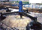
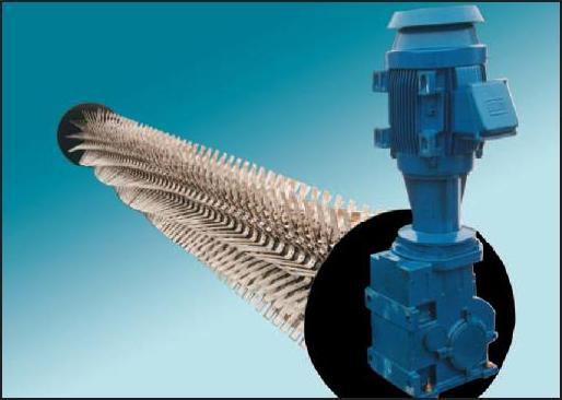
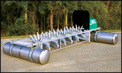
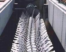
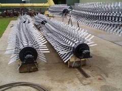
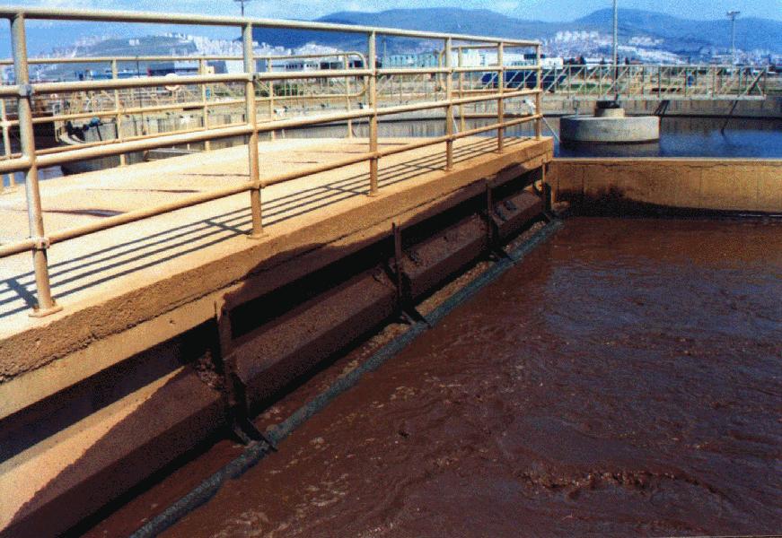
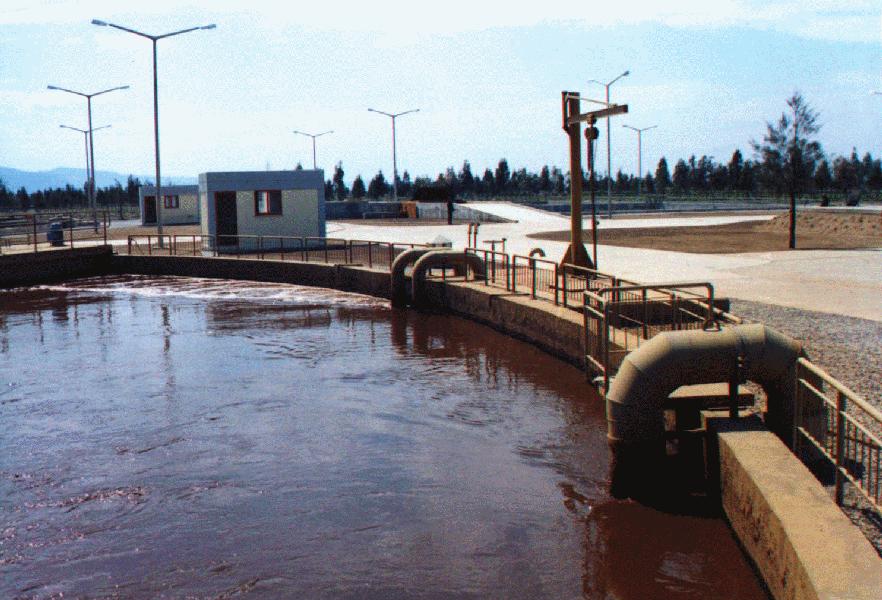
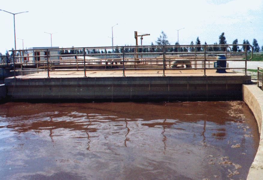
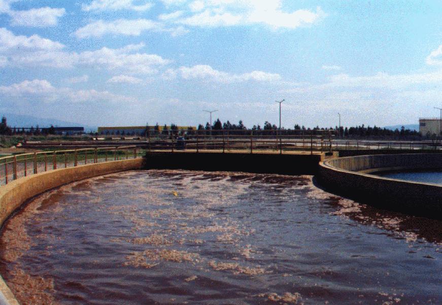
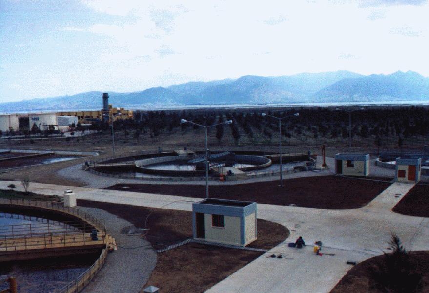
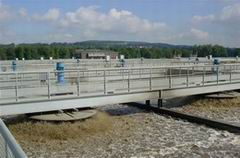
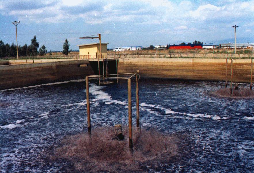
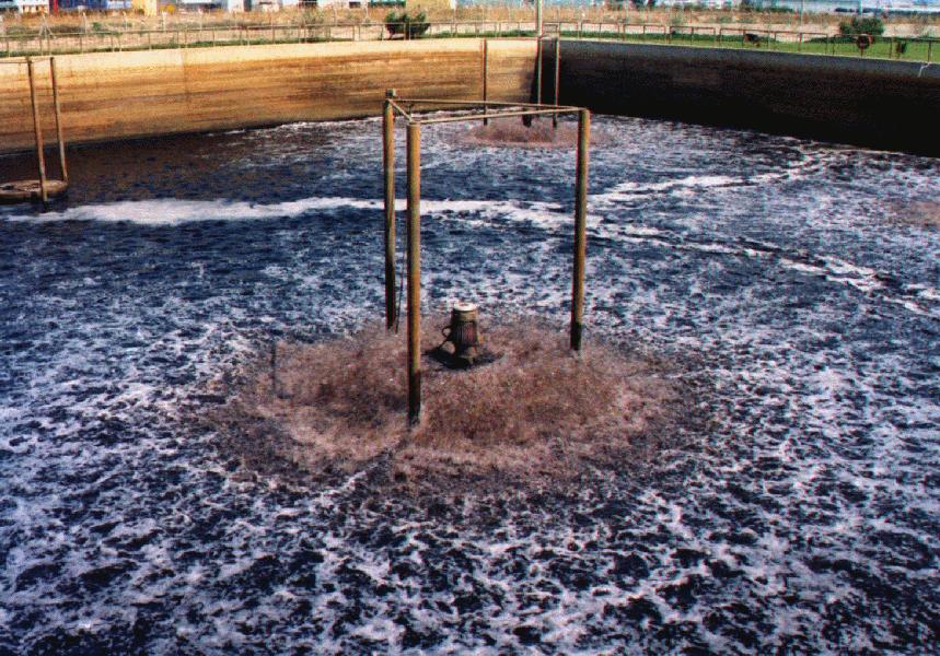
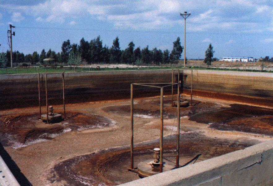
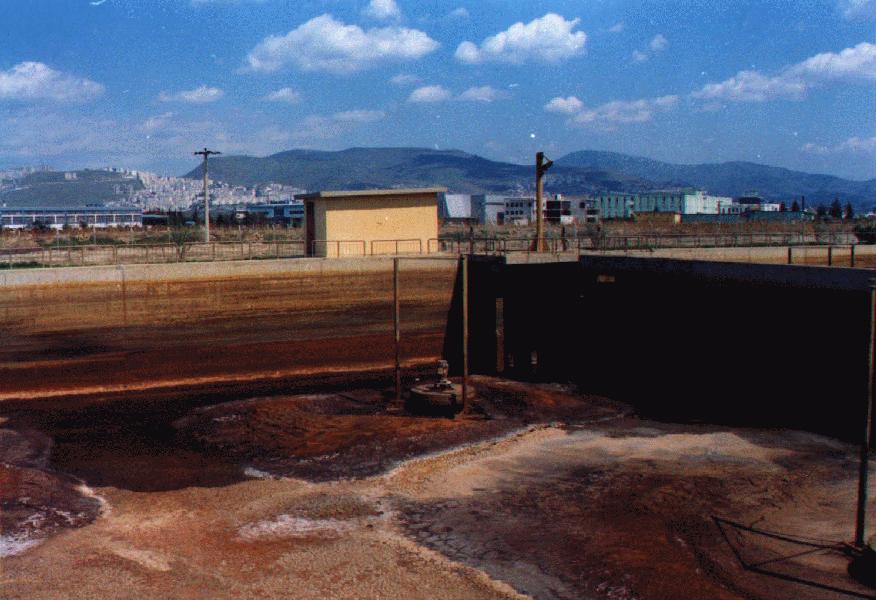
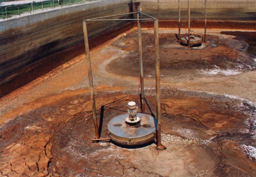
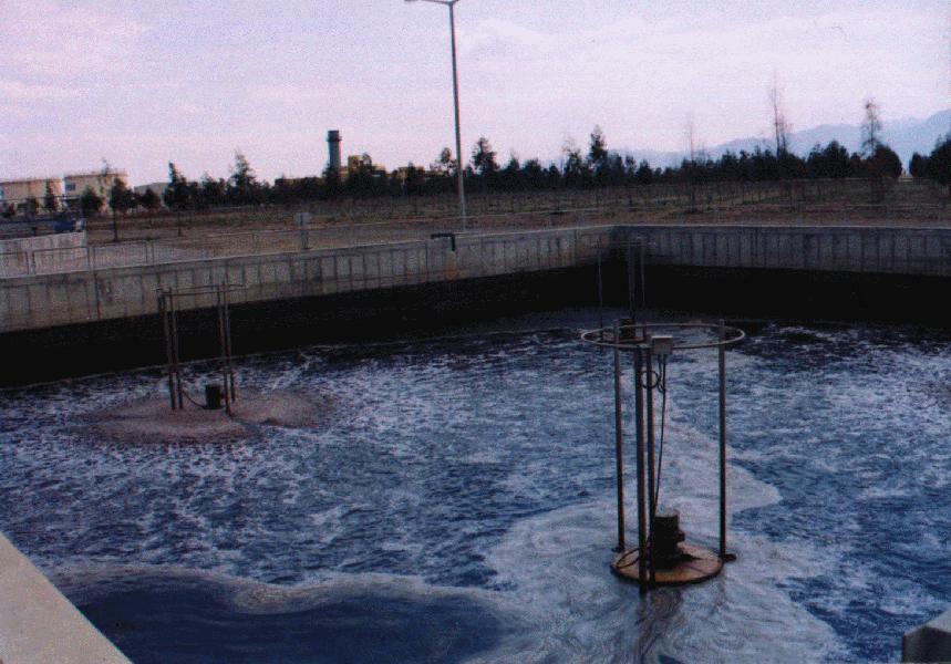
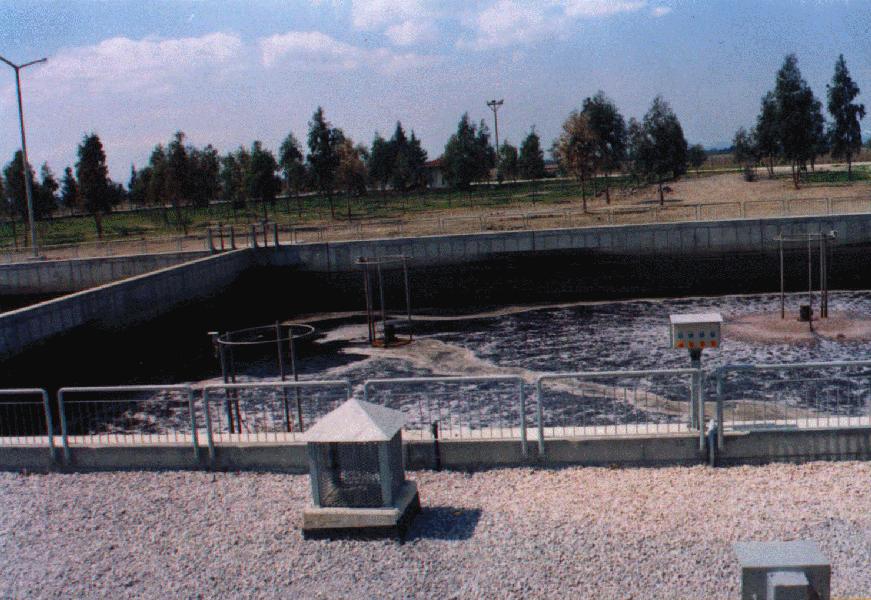
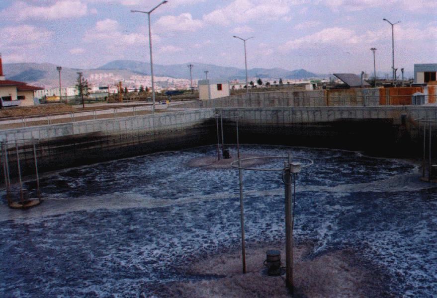
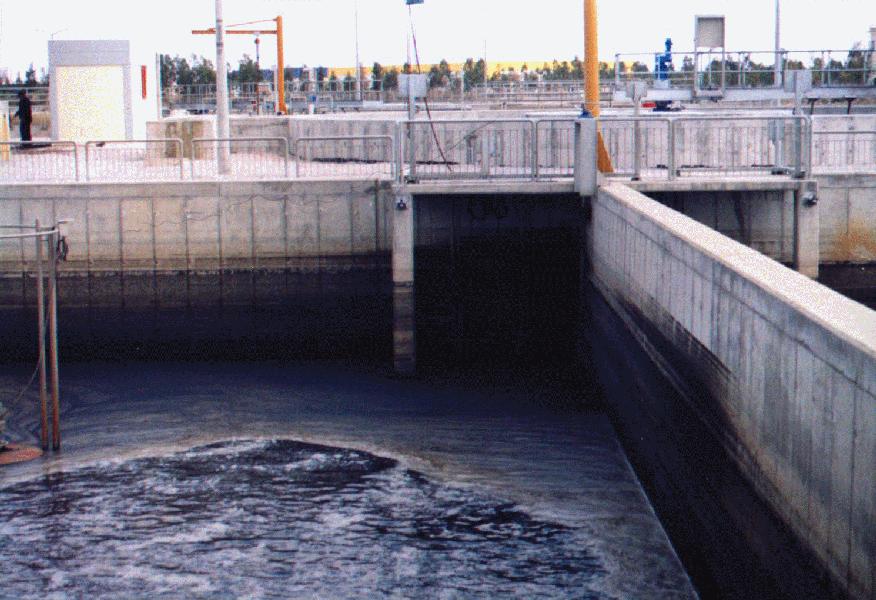
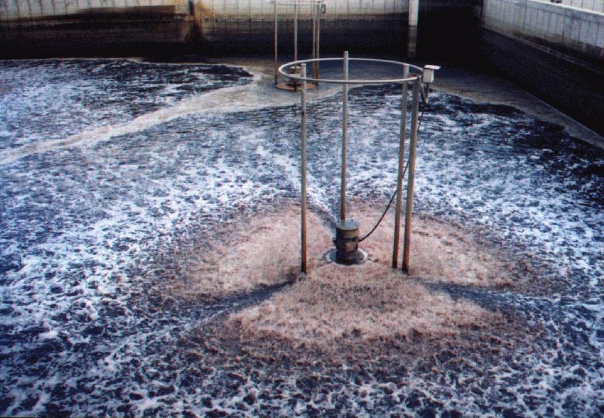
Aeration Equipments from " Passavant - Geiger "
English