Wastewater Treatment Plant Design...

Chapter 01 - Stormwater, Sewers and Sewage...

1.1. General...

Wastewaters are often classified as stormwater, sullage and foul water. Separation of the stormwater from the other two types enables flexibility in storage treatment and disposal methods to be maximized. Sullage and foul sewage are rarely separated.

1.2. Stormwater Sewerage...

Storms vary in intensity ( mm / h ), duration ( h or min ) and frequency ( number of storms of given intensity per 10 years, averaged over a long period ). Bilham formula ;

T = ( 1.25 ) ( t ) [ ( 0.0394 w ) + 0.10 ] - 3.55

where ; w : total rainfall ( mm ) over duration t ( h ), T : number of storms of this intensity ( w / t ) expected in 10 years. The Bilham formula can be used to construct the intensity - duration curve for storms with particular return periods as follows :

Example 1-1 :

For a storm likely to occur 10 times in 10 years ( T = 10 ) and for a duration of 2 h ( t = 2 ).

Calculation :

10 = ( 1.25 ) ( 2 ) [ ( 0.0394 w ) + 0.10 ] - 3.55

The overall rainfall ;

w = ( 1 / 0.0394 ) { [ ( 1.25 ) ( 2 ) / ( 10 ) ]1 / 3.55 - 0.10 } = 14.64 mm

Thus, the intensity = 14.64 / 2 = 7.32 mm / h

Table shown below gives the further values for w, w / t and t and these are plotted in figure given below.

Duration ( h ) Total rainfall ( mm ) Intensity ( mm / h )
0.1 4.85 48.5
0.5 9.08 18.2
1.0 11.59 11.6
1.5 13.30 8.9
2.0 14.64 7.3
3.0 16.72 5.6
4.0 18.34 4.6


It is clear that a 10 year return period storm of a given duration produces approximately twice the rainfall intensity of a storm with a return period of 1 year and the same duration. In practice, a sewer which has been designed to cope with a 1 year return period storm may cope with a 1 in 10 year storm since flows will back up in manholes etc. and pressurize or surcharge the sewer, thus increasing the discharge rate.

1.3. Time of Concentration...

If rain starts to fall over an area A C and is removed in a sewer of length l ( m ), then after some initial delay, referred to as the entry time t E ( min ), storm water from the area closest to the outlet of the sewer will reach the sewer outlet. The discharge at the outlet will increase until eventually the whole area A C is contributing. For the whole area to contribute to the flow, the storm must last until water from the areas furthest from the sewer outlet has entered the sewer and flowed the length of the sewer. The time to flow the length of the sewer plus the time of entry is the "time of concentration" t C for the area ;

t C = ( 1 / 60 V F ) + t E

where ; V F : full bore velocity ( m / s ).

1.4. The Rational Method...

The "Rational Method" of determining the stormwater sewer flow from an area is based on two criteria ;

( a ) Maximum flow occurs when the storm duration is equal to t C .

( b ) Q = ( C ) ( i ) ( A C ).

Table given below shows the impermeability coefficients ( C ).

Type of surface C
Lawns 0.10 - 0.20
Streets 0.70 - 0.95
Residential areas ( flat ) 0.30 - 0.50
Residential areas ( hilly ) 0.50 - 0.70
Urban areas 0.70 - 0.90
Industrial areas ( light ) 0.55 - 0.65
Industrial areas ( heavy ) 0.60 - 0.80

Example 1-2 :

Consider two areas served in series by a continuous sewer. Area 1 is 1.0 ha with an overall coefficient of impermeability C of 0.35 ( residential ) and has a ground slope of 1 in 400. Area 2 is again 1.0 ha with C = 0.25 with a slope of 1 in 300. Choose sewer diameters for the two areas given that the sewer length in area 1 is 150 m, for area 2 is 190 m and the storm return period is 1 year.

Calculation :

- Since the velocity in a sewer should be >= 0.75 m / s an approximate value for t C in area 1 is given by assuming V F = 0.85 m / s. A value for t E of 2.5 min has been chosen to illustrate the method.

t C - GUESSED = { ( 150 ) / [ ( 60 ) ( 0.85 ) ] } + 2.5 = 5.4 min

i = ( 750 ) / ( 10 + 5 ) = 50 mm / h

Q 1 = ( C ) ( i ) ( A ) = [ ( 0.35 ) ( 50 ) ( 10,000 ) ( 10 - 3 ) ] / ( 3,600 ) = 0.049 m 3 / s

From table given below, a sewer of 300 mm diameter laid to a self cleansing gradient of 0.0026 ( 1 in 385 ) would be satisfactory and would carry 0.053 m 3 / s. Other alternatives would be a 250 mm diameter sewer laid to a slope of 0.007 ( 1 in 143 ). However this latter choice would increase V F to 1.08 m / s ; thus diminishing t C to [ ( 150 ) / ( 1.08 ) ( 60 ) ] + 2.5 or 4.8 min and therefore increasing i by a small amount. Savings in cost of pipe would have to be offset against the increased excavation depth caused by the slope of 1 in 143. Assuming the 300 mm diameter pipe is chosen, the value of V F for the sewer when carrying 0.049 m 3 / s is approximately that of full bore flow, i.e. 0.75 m / s. The use of this value for V F would increase t C to 5.8 min and reduce i to 47 mm / h with consequent reduction in Q 1 to 0.046 m 3 / s.

Pipe diameter ( mm ) Minimum gradient ( m / m ) Flowrate ( m 3 / s )
100 0.0111 0.006
150 0.0064 0.013
200 0.0044 0.024
225 0.0038 0.030
250 0.0033 0.037
300 0.0026 0.053
375 0.0019 0.083
450 0.0015 0.120
525 0.0012 0.163
600 0.0010 0.212
( Based on self cleansing velocity of 0.75 m / s and a Manning's coefficient n = 0.012 )

- Area 2 : For a sewer length of 190 m, estimating V F as 0.85 m / s leads to a flow time in this length of 3.7 min. Adding the value of t C for area 1 gives a total time t C for the combined area of 3.7 + 5.8 = 9.5 min. Therefore ;

i = 750 / 19.5 = 38 mm / h

The sum of ( C ) ( A ) for the two areas is 0.35 x 10 4 + 0.25 x 10 4 or 0.6 x 10 4 m 2 . Therefore the combined flow Q 1 + 2 = ( 38 / 3,600 ) ( 0.6 x 10 4 ) ( 10 - 3 ) = 0.063 m 3 / s. This could be carried by a 375 mm diameter pipe laid to a self cleansing slope of 0.0019 ( 1 in 526 ) but since the ground slopes at 0.0033 ( 1 in 300 ), a 300 mm diameter pipe laid to a slope of 0.0038 ( 1 in 260 ) would also suffice. At this slope the velocity would be 0.92 m / s which would reduce t C overall to ;

t C = [ ( 190 ) / ( 0.92 ) ( 60 ) ] + 5.8 or 9.2 min

which would again result in i being 39 mm / h. This latter choice may therefore be cheaper than the 375 mm diameter pipe.

1.5. Flow in Pipes...

For unpressurized pipe flow conditions, Manning's formula is ;

V = ( 1 / n ) ( r 2 / 3 ) ( S 1 / 2 )

where ; V : velocity ( m / s ), n : Manning's coefficient ( = 0.012 ), r : hydraulic radius ( m ) and S : slope ( m / m ).


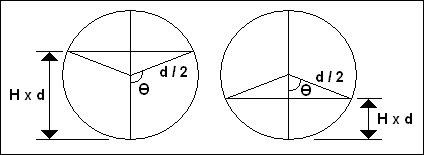
( d / 2 ) ( Cos THETA ) = ( d / 2 ) - ( H ) ( d )

THETA = Cos - 1 ( 1 - 2 H )

A = [ ( THETA ) ( d 2 ) / 4 ] - ( d / 2 ) ( Sin THETA ) ( d / 2 ) ( Cos THETA )

A = ( d 2 / 4 ) [ THETA - ( Sin THETA ) ( Cos THETA ) ]

P = ( THETA ) ( d )

( Note : P is wetted perimeter, d is radius and r is hydraulic radius. )

r = ( d / 4 THETA ) [ THETA - ( Sin THETA ) ( Cos THETA ) ]

( V H / V F ) = { ( d / 4 THETA ) [ THETA - ( Sin THETA ) ( Cos THETA ) ] / ( d / 4 ) } 2 / 3

( V H / V F ) = { ( 1 / THETA ) [ THETA - ( Sin THETA ) ( Cos THETA ) ] } 2 / 3

( Q H / Q F ) = { ( 1 / THETA ) [ THETA - ( Sin THETA ) ( Cos THETA ) ] } 2 / 3 { ( d 2 / 4 ) [ THETA - ( Sin THETA ) ( Cos THETA ) ] / [ ( PI ) ( d 2 / 4 ) ] }

( Q H / Q F ) = ( 1 / PI ) ( 1 / THETA ) 2 / 3 [ THETA - ( Sin THETA ) ( Cos THETA ) ] 5 / 3

Example 1-3 :

For a depth of flow of 0.20 d, i.e. H = 0.20, calculate the velocity and flow as a fraction of the full bore values.

Calculation :

THETA = Cos - 1 ( 1 - 2 x 0.20 ) = 0.927 radians

( V 0.20 / V F ) = [ ( 1 / 0.927 ) ( 0.927 - 0.480 ) ] 2 / 3 = 0.62

( Q 0.20 / Q F ) = ( 1 / PI ) ( 1 / 0.927 ) 2 / 3 [ 0.927 - ( 0.799 ) ( 0.600 ) ] 5 / 3 = 0.088

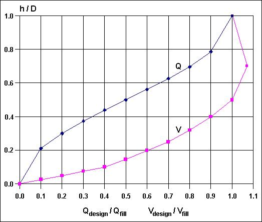
Figure given below shows the variation of the ratios of ( Q H / Q F ) and ( V H / V F ) with depth of flow H. Two features are noteworthy, namely, the value of the velocity is the same for H = 0.50 as for full bore, and the pipe flow appears to be a maximum at H = 0.94.


When H = 0.50 ;

THETA = Cos - 1 ( 1 - 2 x 0.50 ) = 1.571 radians

( V 0.50 / V F ) = [ ( 1 / 1.571 ) ( 1.571 - 1.00 x 0.00 ) ] 2 / 3 = 1.00

This result could have been seen by inspection since the term A / P is precisely the same value for H = 1.00 and H = 0.50. Similarly, the ratio of the areas is seen to be ;

( A 0.50 / A F ) = 1 / 2

so ;

( Q 0.50 / Q F ) = 0.50

where ; A F is the total cross - sectional area of the pipe. Thus the 1 / 2 full bore discharge is 50 % of that running full.

When H = 0.94 ;

THETA = Cos - 1 ( 1 - 2 x 0.94 ) = 2.65 radians

( Q 0.94 / Q F ) = 1.08

i.e. the discharge is at its maximum value of 108 % of the full bore discharge.

For more info about the "Sanitary Sewer Design"...

1.6. Foul Sewerage...

Foul sewerage calculations are usually based on the concept of dry weather flow ( DWF ) which is the average daily flow in the sewer after several days during which the rainfall has not exceeded 0.25 mm. A formula is often used where direct measurement cannot be made, i.e. ;

DWF = ( N ) ( G ) + I + T ( L / day )

where ; N : population served by the sewer, G : average daily per capita water usage ( L / capita . day ), I : average ( dry weather ) infiltration into the sewer owing to poor joints or pervious materials etc. ( L / day ) and T : average trade waste discharge ( L / day ).

Example 1-4 :

A septic tank serves a house containing 4 persons discharging 180 L / capita . day by means of a 100 mm ( 4 in ) diameter sewer pipe. If surface water is totally excluded the following multiples of DWF occur ;

DWF = [ ( 4 ) ( 180 ) ] / ( 8.64 x 10 4 ) = 0.0083 L / s

At night the flow will be almost zero. When 1 x 10 L WC is flushed in 10 s the flow is 1 L / s or 120 DWF. When 1 x 50 L bath is discharged over 30 s the flow is 201 DWF.

Example 1-5 :

In a mainly residential area of 100 persons / ha the per capita daily water usage is 220 L / capita . day. Compare the foul sewage flow with a stormwater flow produced by an intensity of rainfall of 40 mm / h when C = 0.35 for the district.

- For the foul sewage ;

DWF = ( 220 ) ( 100 ) = 22,000 L / ha . day = 22.00 m 3 / ha . day

- At a peak flow of 6 DWF this is 1.50 L / ha . s

- For the storm flow ;

Q = ( 0.35 ) ( 40 / 3,600 ) ( 10 4 ) ( 10 - 3 ) = 0.039 m 3 / s = 39 L / s

- The ratio is therefore 1 : 26 of foul sewage to storm water.

- When calculating the diameter of a foul water sewer on a totally separate system, an estimate must be made of the inflow to the sewer of infiltration water owing to poor joints or pervious materials. A figure of 120 L / km . h of new sewer has been used in the UK with somewhat larger 200 L / km . h values being common in the USA.

Example 1-6 :

3 sewers each 300 m long are to be constructed to each serve 75 houses. The occupancy rate is 3.7 per house and the water consumption is 240 L / capita . day. The 3 sewers feed a larger sewer 200 m long which has additionally to serve 50 houses. Determine suitable pipe diameters and slopes when the ground slope is 1 in 100.

- For each of the 3 sewers the average domestic flow is ;

DWF ( Less infiltration ) = ( 240 ) ( 3.7 ) ( 75 ) = 66,600 L / day

- Ignoring the infiltration water, 6 DWF is 4.6 L / s. From table above, a 100 mm sewer laid at 0.011 slope ( 1 in 91 ) would accommodate 5.9 L / s.

- At 6 DWF the ratio of ( Q H / Q F ) would be 0.78. From figure above, H would be 0.67 and the corresponding velocity would be 1.1 x the full bore velocity of 0.75 m / s.

- Barlett has suggested that the sewer should be designed to reach a self cleansing velocity once a day and he has also suggested that 2 DWF is the maximum flow that can be relied upon to occur at least once a day. Therefore the sewer should produce a flow velocity of >= 0.75 m / s at 2 DWF.

- Now 2 DWF = 1.5 L / s. Therefore ;

( Q H / Q F ) = 0.25 ; H = 0.37 ; ( V 0.37 / V F ) = 0.89

- Therefore V H at 2 DWF = ( 0.89 ) ( 0.75 ) = 0.67 m / s, which is unsatisfactory. Increasing the slope to 0.020 ( 1 in 50 ) increases Q F to ;

Q F = ( 5.9 ) [ ( 0.020 ) 1 / 2 / ( 0.011 ) 1 / 2 ] = 8.0 L / s

- Thus at 2 DWF ;

( Q H / Q F ) = 0.19 ; H = 0.29 ; ( V 0.29 / V F ) = 0.77

- Thus at 2 DWF ;

V = ( 0.77 ) ( 0.33 ) ( 100 ) 2 / 3 ( 0.02 ) 1 / 2 = 0.77 m / s

This indicates quite clearly the considerable problems, with even the minimum size of sewer, in achieving self cleansing velocities.

- For a 150 mm diameter sewer at 2 DWF ;

( a ) At slope 0.0064 ; ( Q H / Q F ) = 0.11 ; H = 0.2 ; ( V 0.2 / V F ) = 0.6 ; V 0.2 = 0.45 m / s

( b ) At slope 0.02 ; ( Q H / Q F ) = 0.06 ; H = 0.15 ; ( V 0.15 / V F ) = 0.5 ; V 0.15 = 0.66 m / s

- For the sewer after the junction of the 3 minor sewers ;

6 DWF = ( 4.6 ) ( 3 ) + 3.0 = 16.8 L / s

A 150 mm diameter sewer at a slope 0.012 ( 1 in 83 ) would carry 18.1 L / s at a velocity of 1.02 m / s and at 2 DWF. ( Q H / Q F ) = 0.31 ; H = 0.37 and ( V 0.37 / V F ) = 0.86 ; thus V 0.37 = 0.88 m / s. A 150 mm diameter sewer at a slope of 0.012 ( 1 in 83 ) is therefore satisfactory.