Wastewater Treatment Plant Design...

Chapter 04 - Secondary Treatment...

4.1. Biological Kinetics...

The Monod equation relating the specific growth rate of bacteria to substrate concentration has been shown to be applicable to sewage treatment and is given as ;

MU = [ ( MU MAX ) ( S E ) ] / ( K S + S E )

where ; S E : substrate concentration ( BOD or COD in mg / L ) which may be interpreted as the substrate concentration in the outlet stream from a mixed microbiological reactor ( e.g. an extended aeration tank ), K S : constant ( mg / L ) and has the value of S E when MU = MU MAX / 2, and MU MAX : maximum value of the specific growth rate MU ( 1 / time ). The specific growth rate is defined as ;

MU = ( 1 / X ) ( dX / dt )

where ; X : biomass concentration ( mg / L ) and t : time. Integration of the equation when MU MAX is at its maximum value MU gives ;

ln ( X / X O ) = ( MU MAX ) ( t )

which can be used to give a generation time or the doubling time for a bacterial population.

Example 4-1 :

The value of MU MAX for common sewage bacteria has been quoted as 0.10 1 / h and for the nitrifying bacteria responsible for nitrate formation as 0.08 1 / day. Calculate the generation time for these two types of organisms, and plot the Monod curve for the sewage bacteria if K S = 55 mg / L as COD. Hence find the generation time when S E = 40 mg COD / L.

Calculation :

The doubling time or generation time, t G , is given by ;

t G = ( 1 / MU MAX ) ln ( 2 X O / X O )

Therefore for the wastewater bacterium ;

t G = ln ( 2 ) / 0.10 = 6.9 h

and for the nitrifying organisms ;

t G = ln ( 2 ) / 0.08 = 8.7 days

If ;

MU = [ ( MU MAX ) ( S E ) ] / ( K S + S E )

then for S E = 10 mg COD / L

MU = [ ( 0.10 ) ( 10 ) ] / ( 55 + 10 ) = 0.015 1 / h

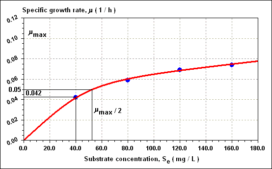
and similarly for other values of S E . Figure given below may be drawn from which a value of 0.042 1 / h for MU is found when S E = 40 mg / L. Thus, t G at 40 mg COD / L = 16.5 h.

4.2. Activated Sludge - Operating Criteria...

4.2.1. High Rate System...

It can be shown from the Monod equation that under maximum growth conditions ( MU = MU MAX ) ;

ln [ 1 + ( Y ) ( L R ) / ( X O ) ] = ( MU MAX ) ( t )

where ; L R : BOD removed ( mg / L ), X O : MLSS concentration ( mg / L ) and Y : yield of biomass.

( dX / dS ) = - Y

The negative sign implies a positive value for dX and Y when S is diminishing. The above equations can be used to determine aeration times for high strength wastes.

Example 4-2 :

An activated sludge unit treats a food processing waste of 0.01 m 3 / s with a BOD of 1,500 mg / L for which MU MAX = 0.10 1 / h and Y = 0.60. If a MLSS value of 3,000 mg / L is kept constant, and the returned sludge concentration is 11,000 mg / L, calculate the aeration volume required to give an effluent concentration, S E of 50 mg / L.

Calculation :

Consider the settlement tank solids balance ;

( F + q ) ( X O ) = ( q ) ( X U )

where ; F and q : influent sewage and returned sludge flow rates, respectively ( m 3 / s ). Thus ;

( F / q ) = ( 11,000 - 3,000 ) / ( 3,000 ) = 2.7

q = ( F ) / ( 2.7 ) = ( 0.01 ) / ( 2.7 ) = 0.0037 m 3 / s

The retention time t is given by ;

t = ( 1 / 0.10 ) ln [ 1 + ( 0.60 ) ( 1,500 - 50 ) / ( 3,000 ) ] = 2.5 h

Total flow rate = 0.01 + 0.0037 = 0.0137 m 3 / s

Tank volume = ( 2.5 ) ( 3,600 ) ( 0.0137 ) = 123 m 3

4.2.2. Conventional System...

There are two equations ;

For BOD > 250 mg / L ;

L E = ( L I ) - ( 250 - 9.3 ) [ ( J ) ( t ) ( X ) / ( 2,000 ) ]

For BOD <= 250 mg / L ;

L E = ( 9.3 ) + ( L I - 9.3 ) exp - [ ( J ) ( t ) ( X ) / ( 2,000 ) ]

where ; J : parameter defined at temperature T O C as ;

J = ( 0.0073 ) ( T 2 ) - ( 0.0827 ) ( T ) + 0.7162

where ; L E and L I : effluent and influent BOD concentrations, respectively.

Example 4-3 :

For an activated sludge tank treating 0.05 m 3 / s of settled sewage of 275 mg / L BOD, calculate the retention time and aeration tank volume required to produce an effluent of 20 mg / L when the MLSS is 2,000 mg / L and the lowest daily temperature is 8 O C.

Calculation :

For the linear portion of a BOD / t plot, i.e. from 275 to 250 mg / L BOD ;

250 = ( 275 ) - ( 250 - 9.3 ) [ ( J ) ( t ) ( X ) / ( 2,000 ) ]

J = ( 0.0073 ) ( 8 2 ) - ( 0.0827 ) ( 8 ) + 0.7162 = 0.52

t = [ ( 250 - 275 ) ( 2,000 ) ] / [ - ( 240.7 ) ( 0.52 ) ( 2,000 ) ] = 0.20 h

For 250 to 20 mg / L ;

20 = ( 9.3 ) + ( 250 - 9.3 ) exp - [ ( 0.52 ) ( t ) ( 2,000 ) / ( 2,000 ) ]

t = 6.0 h

The total time is 6.0 + 0.2 = 6.2 h and tank volume is ( 6.2 ) ( 3,600 ) ( 0.05 ) = 1,120 m 3

4.2.3. Decay Stage - Aerobic Digestion...

When the food source is fully depleted the bacteria break down according to the expression ;

( dX / dt ) = - ( K D ) ( X )

where ; K D : endogenous or decay rate constant. Integration gives ;

ln ( X / X O ) = - ( K D ) ( t )

Because it is the organic ( volatile ) fraction that is decaying, it is usual to express the equation in terms of the volatile biomasses X V and X V - O and a volatile decay constant K D ' ;

ln ( X V / X V - O ) = - ( K D ' ) ( t )

The process of aerobically storing sludge and allowing it to decay is called aerobic digestion and is used where anaerobic digestion is not practicable, for example, in the case of small scale units serving small populations.

Example 4-4 :

3 m 3 of excess activated sludge of 75 % volatile matter at 8,000 mg / L is aerobically digested for 10 days. The sludge is then settled to a 1.5 % slurry and transported from the site ; what is the transported volume if K D ' = 0.07 1 / day.

Calculation :

3 m 3 at 8,000 mg / L total solids = 3 m 3 at 6,000 mg organics / L. Therefore, after 10 days aerobic digestion, the concentration of organic material is ;

X V = ( X V - O ) exp ( - K D ' 10 ) = ( 6,000 ) exp ( - 0.07 x 10 ) = 2,980 mg / L

which is equivalent to a total solids concentration of 2,980 + 2,000 = 4,980 mg / L assuming the 2,000 mg / L inorganic solids remain intact. The total mass is 4,980 x 10 - 6 x 3 x 10 3 = 14.9 kg. At 1.5 % solids ( 15,000 mg / L or 15 kg / m 3 ), the total volume transported is 14.9 / 15 = 1 m 3 .

4.2.4. Sludge Age and Sludge Loading...

The sludge age or mean cell residence time, THETA C , for an activated sludge unit is defined as ;

THETA C = ( Mass of sludge solids in the aeration tank, kg ) / ( Mass of sludge solids wasted daily, kg / day )

and has units of days. This may be expressed as ;

THETA C = [ ( V ) ( X O ) ] / [ ( F W ) ( X O ) ]

where ; V : aeration tank volume, X O : MLSS concentration and F W : daily waste flow of excess sludge. A common estimate of excess sludge production would be 0.60 kg dry sludge solids per kg BOD removed. The sludge loading ratio is defined as ;

SLR = ( Mass of BOD 5 input to aeration tank, kg / day) / ( Mass of MLSS in aeration tank, kg )

and has units of kg BOD 5 / kg MLSS . day. It also be written ;

SLR = [ ( F ) ( L I ) ] / [ ( V ) ( X O ) ]

where ; F : sewage inflow. This is also known as the food : microorganism ratio ( F : M ).

Example 4-5 :

Table given below lists some operating parameters for two common types of activated sludge plant. Calculate the values of THETA C and the SLR for each case.

Parameter Conventional activated sludge Extended aeration
BOD load 0.04 kg / capita . day
( After settlement )
0.06 kg / capita . day
Aeration volume 50 - 70 L / capita . day 230 L / capita . day
Sludge wasting 0.60 kg / kg BOD removed 0.50 kg / kg BOD removed
MLSS 3,000 mg / L 3,000 mg / L

Calculation :

For conventional activated sludge ;

THETA C = [ ( 50 ) ( 3,000 ) ( 10 - 6 ) ] / [ ( 0.04 ) ( 0.60 ) ] = 6.3 days
SLR = ( 0.04 ) / ( 0.15 ) = 0.27 kg BOD 5 / kg MLSS . day

For extended aeration ;

THETA C = [ ( 230 ) ( 3,000 ) ( 10 - 6 ) ] / [ ( 0.06 ) ( 0.50 ) ] = 23 days
SLR = ( 0.06 ) / ( 0.69 ) = 0.09 kg BOD 5 / kg MLSS . day

It should be noted that in addiition to the sludge actually wasted, approximately 4 g / capita . day of sludge solids may pass over the outlet weir in the effluent stream. Also the MLSS may vary from 2,000 mg / L up to 6,000 mg / L. Both these effects can cause considerable variations in values of THETA C . The sludge loading ratio may be modified to become the sludge utilization rate ( SUR ) which is defined as ;

SUR = ( Mass of BOD removed, kg / day ) / ( Mass of volatile solids in reactor, kg ) = [ ( F ) ( L R ) ] / [ ( V ) ( X V - O ) ]

and has units of 1 / day. Often only the MLSS ( X O ) is measured as opposed to the mixed liquor volatile suspended solids ( X V - O ), in which case the SUR may be expressed as [ ( F ) ( L R ) ] / [ ( V ) ( X O ) ]. A relationship between X V - O and X O has been given as ;

( MLVSS / MLSS ) ( X V - O / X O ) = ( 0.85 ) / ( THETA C 0.10 )

Example 4-6 :

Two separate activated sludge processes treat identical sewage flows of 200 L / capita . day with inlet and outlet BODs 300 mg / L and 20 mg / L. The aeration volumes are, for plant 1 ; 0.070 m 3 / capita with THETA C = 6 days ; and for plant 2 ; 0.230 m 3 / capita with THETA C = 15 days. If the MLSS in each case is 3,000 mg / L, calculate the SUR values for the two processes.

Calculation :

X V - O - 1 = ( 3,000 ) ( 0.85 ) / 6 0.10 = 2,130 mg / L = 2.30 kg / m 3
X V - O - 2 = ( 3,000 ) ( 0.85 ) / 15 0.10 = 1,950 mg / L = 1.95 kg / m 3

The mass of BOD removed in each case is ;

BOD REMOVED = ( 200 ) ( 300 - 20 ) = 56,000 mg / capita . day = 0.056 kg / capita . day

SUR 1 = ( 0.056 ) / ( 0.07 ) ( 2.13 ) = 0.38 kg BOD / kg MLVSS . day
SUR 2 = ( 0.056 ) / ( 0.23 ) ( 1.95 ) = 0.12 kg BOD / kg MLVSS . day

4.2.5. Sludge Yield Coefficient...

When a mass of BOD is utilized in a set time interval ( dS / dt ) a mass of new cells is produced ( dX V / dt ) thus ;

( dX V / dt ) = ( Y ) ( dS / dt )

Y is constant over a range of SUR values and is the yield coefficient.

4.2.6. Sludge Growth and Sludge Wasting...

An expression relating the sludge age THETA C in terms of the yield coefficient can be derived with the help of a diagram of an activated sludge system showing the biomass flows.


A continuity equation for the volatile component of the sludge for a completely mixed activated sludge system ( CMAS ) is ;

( F ) ( X V - I ) + ( dX V - O / dt ) ( V ) = ( F - F W ) ( X V - E ) + ( F W ) ( X V - W )

where ; suffixes I, E and W represent inlet, effluent and waste flows, respectively. ( dX V - O / dt ) ( V ) is the cell growth in the reactor.

Now ;

( dX V - O / dt ) = ( Y ) ( dS / dt ) - ( K D ' ) ( X V - O )

Thus if X V - I and X V - E are small with respect to X V - W and ( dX V / dt ), dividing by ( X V - O ) ( V ) gives ;

( Y / X V - O ) ( dS / dt ) - K D ' = [ ( F W ) ( X V - W ) ] / ( X V - O ) ( V )

Now the ratio of ( X V - W / X V - O ) is the same as the ratio ( X W / X O ) since the volatile fraction is similar in X W and X O . Thus ;

{ [ ( F W ) ( X W ) ] / [ ( X O ) ( V ) ] } = { [ ( F W ) ( X V - W ) ] / [ ( X V - O ) ( V ) ] }

( 1 / THETA C ) = ( Y ) ( SUR ) - K D '

Values for Y and K D ' are conventionally 0.70 and 0.08 1 / day, respectively, thus for many plants ;

( W V / M B ) = 0.70 - ( 0.08 ) ( M V / M B ) ( K )

where ; W V : sludge to be wasted ( kg / day ), M B : total mass of BOD removed ( kg / day ) and M V : total MLVSS in the reactor ( kg ). K is a constant with value 1.00 but with dimension T - 1 and units of 1 / day.

Example 4-7 :

A wastewater treatment plant treats a per capita flow of 200 L / day from a population of 10,000. The inlet and outlet BODs are 350 mg / L and 20 mg / L, respectively. If the aeration tank has 3,000 mg / L MLVSS and a capacity of 0.07 m 3 / capita, calculate the volume of sludge to be wasted assuming a settled sludge concentration of 10,000 mg / L as volatile solids.

Calculation :

M B = ( 10,000 ) ( 200 ) ( 350 - 20 ) ( 10 - 6 ) = 660 kg / day

M V = ( 0.07 ) ( 10,000 ) ( 3,000 ) ( 10 - 3 ) = 2,100 kg

Thus ;

W V = ( 0.70 ) ( 660 ) - ( 0.08 ) ( 2,100 ) = 294 kg / day of volatile solids ( dry )

Which, at 10,000 mg / L ( 1 % solids ) is equivalent to 29.4 m 3

An empirical expression is ;

W V = ( F ) ( L I ) ( 0.20 + SLR 1 / 2 )

Example 4-8 :

For the sludge considered in Example 4-7 calculate the volume of sludge to be wasted if the waste sludge is 75 % organic.

Calculation :

( F ) ( L I ) = ( 10,000 ) ( 200 ) ( 350 ) ( 10 - 6 ) = 700 kg / day

SLR = ( 700 ) / ( 2,100 / 0.75 ) = 0.25 1 / day

W V = ( 700 ) ( 0.20 + 0.25 1 / 2 ) = 490 kg / day = 49 m 3

4.3. Aeration...

The transfer of oxygen to water is governed by physical laws. The saturation concentration of oxygen in pure water ( C S , mg / L ) at T O C is given by ;

C S = 14.61 - ( 0.3943 ) ( T ) + ( 0.007714 ) ( T 2 ) - ( 0.0000646 ) ( T 3 )

For sewage, C S is approximately 85 - 90 % of C S for pure water. The mass of oxygen transferred per unit time ( dm / dt ) is proportional to the difference between the actual concentration of oxygen in the liquid C and the saturation value C S ;

( dC / dt ) = ( K L - A ) ( C S - C )

Dissolved oxygen deficit ;

D = C S - C

dD = - dC

( dD / D ) = ( K L - A ) ( dt )

( D / D O ) = exp ( - K L - A x t )

ln ( D / D O ) = ( - K L - A x t )

However, in the context of sewage treatment it is more useful to express the last equation as ;

ln [ ( C S - C ) / ( C S - C O ) = ( - K L - A x t )

where ; C O is the value of C when t = 0.

Example 4-9 :

Two aerators are used to aerate separate, equal volumes of water which have been previously deaerated by the addition of sodium sulphite catalysed by cobalt chloride. The oxygen concentrations were read at different times using a dissolved oxygen probe. Calculate the K L - A values for the two aerators and hence calculate the maximum capacity of both aerators. ( Water temperature is 16 O C ).

Time ( s ) 0 250 500 750 1,000 1,250 1,500
Aerator-1 DO ( mg / L ) 0 4.4 6.8 8.2 9.0 9.4 9.7
Aerator-2 DO ( mg / L ) 0 2.2 3.8 5.0 6.1 7.3 7.6

Calculation :

For 16 O C, C S = 10.0 mg / L which is the asymptotic value in table given above. For t = 500 s for aerator-1, the oxygen concentration is 6.8 mg / L. Thus ;

ln [ ( C S - C ) / ( C S - C O ) = ln [ ( 10 - 6.8 ) / ( 10 - 0 ) = - 1.14

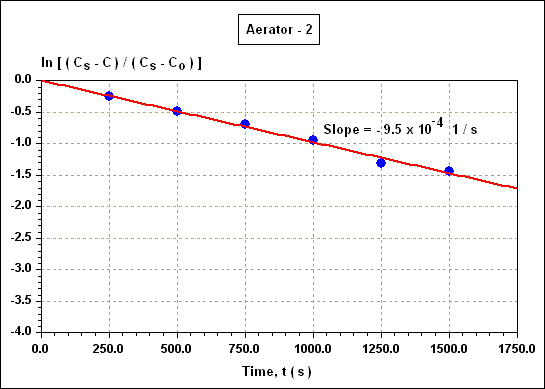
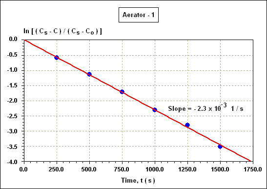
Similarly the other values for ln [ ( C S - C ) / ( C S - C O ) can be calculated and plotted against time t as in figures given below.


This gives slopes of - 2.3 x 10 - 3 1 / s and - 9.5 x 10 - 4 1 / s for K L - A for aerators 1 and 2, respectively. The maximum capacities, or the maximum rate, of input of oxygen into to solution is given by ( dm / dt ) ( V ) = ( K L - A ) ( C S ) ( i.e. when C = 0 ). Thus capacities of 2.3 x 10 - 2 mg / L . s and 9.5 x 10 - 3 mg / L . s are found for aerators 1 and 2, respectively.

The oxygenation capacity of a given aerator in practice is affected by many different factors, including barometric pressure changes and the presence of organics and synthetic detergents. One expression which enables an experimental value of oxygenation capacity ( OC ) to be related to standard conditions is ;

OC EXP = ( ALPHA ) ( OC STD ) { [ ( BETA ) ( C S ) - ( C ) ] / ( C S ) } [ ( P - P W ) / ( 101.3 - P W ) ]

where ; OC STD : oxygenation capacity for pure water at standard pressure ( 101.3 kN / m 2 or kPa ), OC EXP : oxygenation capacity under experimental conditions with pressure P ( kN / m 2 ), BETA and ALPHA : factors ( usually less than unity ) which allow for changes in C S and K L - A owing to the presence of organics and synthetic detergents and P W : unreacting vapour pressure.

Example 4-10 :

An aerator delivers a maximum of 5 x 10 - 2 g O 2 / L . s in a tank containing pure water at 10 O C at a pressure of 100 kN / m 2 . It is to be used to aerate the same size tank containing sewage for which BETA = 0.90 and ALPHA = 0.95 at 10 O C under a pressure of 87 kN / m 2 . Calculate the loss in maximum oxygenation capacity under these conditions.

Calculation :

P W at 10 O C is 1.2 kN / m 2

OC SEWAGE = ( 5 x 10 - 2 ) ( 0.95 ) ( 0.90 ) [ ( 87.0 - 1.2 ) / ( 101.3 - 1.2 ) ] = 3.7 x 10 - 2 g / L . s

4.3.1. Variation of Oxygen Capacity With Pressure...

The correction of OC values for changes in pressure in the last example may be significant in mountainous countries since pressure varies with altitude Z ( m ) as ;

P ( kN / m 2 ) = ( 101.3 ) { 1 - [ ( 0.13 ) ( Z ) ] / ( 1,000 ) }

The reduction from 100 to 87 kN / m 2 in the last example is therefore equivalent to a change of approximately 1,000 m.

4.3.2. Variation of Oxygen Capacity With Temperature...

( a ) By increasing K L - A thus ;

( K L - A ) T = ( K L - A ) 20 O C ( 1.024 ) T - 20

( b ) By reducing C S in accordance with ;

( dC / dt ) = ( K L - A ) ( C S - C )

These two effects tend to cancel each other out.

Example 4-11 :

For the same conditions as in Example 4-10, calculate the change in oxygenation capacity for a temperature change from 10 O C to 25 O C.

Calculation :

Maximum OC = ( dm / dt ) ( V ) = ( K L - A ) ( C S )

Now, C S values for 10 O C and 25 O C are 11.3 mg / L and 8.4 mg / L, respectively, or, expressed as a ratio 1.35. Values of K L - A are in the ratio ;

1.024 10 - 20 / 1.024 25 - 20 = 0.70

Thus the ratios of the capacities at 10 O C and 25 O C are ;

OC ( 10 O C ) / OC ( 25 O C ) = 1.35 x 0.70 = 0.95

i.e. a change of 5 %. A further correction to the OC sewage value in Example 4-10 if the sewage were at 25 O C, would be to divide the value of 3.7 x 10 - 2 g / L . s by 0.95, i.e. ;

OC SEWAGE = 3.9 x 10 - 2 g / L . s

4.3.3. Aeration Economy and Efficiency...

For both mechanical aerators and diffusers an overall efficiency of approximately 1.60 to 1.80 kg O 2 / kWh ( 0.44 to 0.50 mg O 2 / J ) can be estimated. Oxygen requirements for different processes are given in the table shown below.

Process kg O 2 / kg BOD removed
Low sludge age ( partial treatment ) 0.90
Conventional ( 20 : 30 : BOD : SS ) 1.20 to 1.30
Extended aeration 2.00

Therefore, for a conventional process, an economy of approximately 1.35 kg BOD removed per kWh is common.

Example 4-12 :

Assuming an oxygen transfer efficiency of 6 %, calculate the air required per capita for an activated sludge plant removing 0.04 kg BOD / capita . day, assuming 1.30 kg O 2 / kg BOD removed. Also calculate the air supply per m 3 aeration capacity given a per capita aeration volume of 70 L.

Calculation :

At NTP ( i.e. 273 O K and 101.3 kN / m 2 ) one gramme molecular weight ( O 2 = 32 g ) is contained in 22.4 L of gas. Since air contains 21 % oxygen, 32 g O 2 are contained in 22.4 / 0.21 = 106.7 L air, or 1 g O 2 is contained in 3.33 L air. At an aeration efficiency of 6 %, 3.33 / 0.06 = 55.6 L of air must be blown or entrained in order to transfer 1 g O 2 . Thus, 0.04 kg BOD requires 1.30 x 0.04 = 0.052 kg O 2 for a conventional process, or, 0.052 kg O 2 is transferred per 52 x 55.5 L = 2.89 m 3 of air blown. This is the per capita air requirement. The air required per m 3 of aeration capacity is ;

( 2.89 ) ( 10 3 / 70 ) = 41.3 m 3 air

4.3.4. Pure Oxygen Systems...

Advantages claimed are reduced overall costs, and, more specifically, smaller aeration tanks, better sludge thickening and lower sludge production rates. The oxygen is either produced by cryogenic air separation or pressure - swing systems. The former method involves liquifying air at - 185 O C and utilizing the different distillation temperatures of the O 2 and N 2 fractions. Table given below lists some commonly quoted operational parameters for pure oxygen systems.

Parameter Air plant Pure oxygen plant
Aeration stage
MLSS ( mg / L ) 3,300 8,000
MLVSS ( mg / L ) 2,500 6,500
Aeration perod ( h ) 4 - 5 1 - 2
Oxygen requirement ( kg O 2 / kg BOD removed ) 1.2 - 1.3 1.3 - 1.4
DO ( mg / L ) 1 - 3 6 - 10
K D ( 1 / day ) 0.10 0.06
Y 0.60 0.05
SLR ( kg BOD / kg MLVSS . day ) 0.2 - 0.3 0.3 - 0.5
Settling stage
Overflow rate ( m 3 / m 2 . day ) 40 - 60 40 - 60
Mass loading ( kg / m 2 . day ) < 200 250
Weir loading ( m 3 / m . day ) < 200 150 - 200

Example 4-13 :

Calculate both the maximum solubility of oxygen in sewage at 10 O C and the increase in oxygenation capacity of an aerator over that for normal air, using an enriched oxygen atmosphere of 90 % O 2 ( volume / volume ).

Calculation :

From ;

C S = 14.61 - ( 0.3943 ) ( T ) + ( 0.007714 ) ( T 2 ) - ( 0.0000646 ) ( T 3 )

C S at 10 O C using normal air at 101.3 kN / m 2 is 11.3 mg / L. From Henry's law ;

C S = ( O 2 % / 100 ) ( P - P W )

Hence for an O 2 % of 90, the value of C S will increase to ( 11.3 ) ( 0.90 ) / ( 0.21 ) = 48.4 mg / L. Multiplying by 0.95 to correct for sewage solids gives a value for C S of 46.0 mg / L. The OC is equal to ( K L - A ) ( C S ) from before. If ( K L - A ) is assumed not to change, the improvement in OC from use of 90 % O 2 enriched air is in the ratio ;

( 48.4 / 11.3 ) ( OC WATER )

i.e. more than a 4 fold increase. From ;

( 1 / THETA C ) = ( Y ) ( SUR ) - K D

or ;

( 1 / THETA C ) = { [ ( Y ) ( F ) ( L R ) ] / [ ( V ) ( X V - O ) ] } - K D

Clearly a plot of 1 / THETA C versus ( L R ) / [ ( t ) ( X V - O ) ] will give a plot with slope Y and ordinate intercept - K D . Such plots have been used to determine values of Y and K D of 0.047 and 0.06 1 / day, respectively, for pure oxygen activated sludge systems compared with respective values of 0.60 and 0.10 1 / day for air. Table given above indicates that one of the most striking differences between air and enriched oxygen units is the high MLVSS values. This gives a considerable reduction in retention time while keeping THETA C value at conventional levels.

Example 4-14 :

The retention time, L R , MLSS, Y and K D values of a conventional plant are 0.20 day, 350 mg / L, 3,500 mg / L, 0.60 and 0.10 1 / day, respectively. The L R , MLVSS, Y and K D values for a pure oxygen system are 350 mg / L, 6,500 mg / L, 0.46 and 0.06 1/ day, respectively. If the THETA C values are the same for both plants, compare the aeration tank retention times for the two processes.

Calculation :

For the plant using normal air ;

( 1 / THETA C ) = { [ ( 0.60 ) ( 350 ) ] / [ ( 0.20 ) ( 3,500 ) ] } - 0.10 = 0.20 1 / day

THETA C - AIR = 5 days

For the pure oxygen plant ;

( 0.20 ) = { [ ( 0.46 ) ( 350 ) ] / [ ( t OXYGEN ) ( 6,500 ) ] } - 0.06

t OXYGEN = 0.095 day = 2.3 h

4.4. Trickling ( Percolating ) Filters...

The simplest form of percolating filter is the single pass system where settled sewage is sprayed onto stone media after which the effluent is collected in under drains and settled to remove dead film. A formula has been proposed to relate the efficiency of BOD removal ( E fraction ) to operating parameters ;

E = 1 / { 1 + ( 0.44 ) [ ( W ) / ( f ) ( V ) ] 1 / 2 }

where ; W : BOD load applied ( kg / day ), f : recirculation factor and V : volume of filter media ( m 3 ). If the filter is a single pass or non - recirculating filter, f = 1.

Example 4-15 :

A single pass filter is to treat 0.01 m 3 / s of settled sewage of 300 mg / L BOD. Calculate the volume and area of filter media necessary to achieve 80 % reduction in BOD.

Calculation :

W = ( 0.01 ) ( 8.64 x 10 4 ) ( 0.30 ) = 259 kg / day

E = 0.80

0.80 = 1 / { 1 + ( 0.44 ) [ ( 259 ) / ( 1.00 ) ( V ) ] 1 / 2 }

V = 802 m 3

An average depth of filter would be 1.80 m giving an area of 446 m 2 . The load is equivalent to approximately 0.32 kg / m 3 . day. A check is needed to ensure that the hydraulic flow rate is within moderate range of 0.50 to 2.50 m 3 / m 3 . day. In the above case the hydraulic loading is ( 0.01 x 8.64 x 10 4 ) / ( 802 ) = 1.08 m 3 / m 3 . day. Note that to achieve a final BOD of 45 mg / L, V = 1,610 m 3 ; the BOD loading rate is 0.16 kg / m 3 . day.

Where the filtration scheme is designed to allow recirculation of the effluent from the secondary settlement tank, the recirculation factor f is defined by ;

f = [ 1 + ( R / F ) ] / [ 1 + ( 0.10 ) ( R / F ) ] 2

where ; R and F represent the recirculated and settled sewage flows, respectively.

Example 4-16 :

For the flow and loading stated in Example 4-15 the filter is to be designed to give a recirculated flow of 0.005 m 3 / s. Calculate the reduction in volume of filter media.

Calculation :

f = [ 1 + ( 0.005 / 0.010 ) ] / [ 1 + ( 0.10 ) ( 0.005 / 0.010 ) ] 2 = 1.36

0.80 = 1 / { 1 + ( 0.44 ) [ ( 259 ) / ( 1.36 ) ( V ) ] 1 / 2 }

V = 590 m 3 or 27 % reduction in volume.

The BOD loading rate is 0.43 kg / m 3 . day and the hydraulic loading rate is ( 0.015 x 8.64 x 10 4 ) / ( 590 ) = 2.2 m 3 / m 3 . day. An alternative expression has been proposed using the hydraulic loading rate, ( F / V ) ( m 3 / m 3 . day ) ; the specific surface area A S ( m 2 / m 3 ) and the temperature T ( O C ), i.e. ;

L E = ( L I ) exp { - [ ( 0.037 ) ( 1.080 ) T - 15 ( A S ) ] / ( F / V ) }

Example 4-17 :

Using the same figures as in Example 4-15 and assuming T = 10 O C and A S = 70 m 2 / m 3 , calculate the filter volume.

Calculation :

L E = ( 0.20 ) ( 300 ) = 60 mg / L

ln ( 60 / 300 ) = [ ( - 0.037 ) ( 1.080 ) 10 - 15 ( 70 ) ] / ( F / V )

( F / V ) = 1.10

V = [ ( 0.010 ) ( 8.64 x 10 4 ) ] / ( 1.10 ) = 785 m 3

Note that a rise in influent sewage temperature to 15 O C would reduce V to 537 m 3

4.5. Rotating Biological Contactors...

They consist of large, 2 - 3 m diameter, discs of braced plastic netting, expanded polystyrene or other material rotating on a shaft at right angles to the sewage flow. They are immersed to about 40 % of their diameter and alternately contact sewage then air. A microbiological film grows on the discs and oxidizes the organic matter in the sewage in a similar manner to a percolating filter. The discs are arranged into baffled groups or stages to prevent short circuiting of the flow. The disc stage is followed by a settling tank in which material sloughing off the disc settles out.

Example 4-18 :

A disc unit is to be designed for a population of 5,000 with a daily per capita water usage of 200 L. The BOD after primary settlement is 0.04 kg / capita . day and the unit is to produce an effluent of <= 20 mg / L BOD.

Calculation :

BOD removal = [ ( 0.04 x 10 6 ) / ( 220 ) ] - ( 20 ) = 162 mg / L

BOD percentage removal = ( 162 ) / ( 182 ) = 89 %

BOD load = ( 5,000 ) ( 0.04 ) = 200 kg BOD / day

Flow = [ ( 5 x 10 3 ) ( 220 x 10 - 3 ) ] / ( 24 x 60 ) = 0.76 m 3 / min

Correction factor = 1.20 ( from table given below )

Persons equivalent Correction factor
10,000 1.00
5,000 - 10,000 1.10 - 1.20
1,500 - 5,000 1.20 - 1.30
400 - 1,500 1.30 - 1.50
400 1.50

Average flow = ( 0.76 ) ( 1.20 ) = 0.92 m 3 / min

From figure given below, in order to achieve 89 % removal at an inlet concentration of 182 mg BOD / L a value of A / Q of 14,650 m 2 . min / m 3 is required where A is the disc area ( m 2 ) and Q is the flow rate ( m 3 / min ) ( corrected ).


The surface area A = ( 14,650 ) ( 0.92 ) = 13,478 m 2

Four shafts or stages are to be used in series ; this should the give required 89 % BOD removal. Increasing the number of stages enables a reduction in area to be made according to table given below.

Number of stages Correction factor Maximum BOD reduction ( % )
3 0.91 85
4 0.87 90
More than 4 0.85 90

Thus ;

A ( Corrected ) = ( 13,478 ) ( 0.87 ) = 11,726 m 2

Assuming 3 m diameter discs are used, with a surface area of 14.1 m 2 ( both sides are used ) the total number of discs required is ( 11,726 ) / ( 14.1 ) = 832, i.e. four stages or shafts each of 208 discs.


A check is required to ensure that the loading on the first stage is not more than 100 g BOD / m 2 . day.

1 ST stage loading = [ ( 5,000 ) ( 0.04 x 10 3 ) ] / [ ( 14.1 ) ( 208 ) ] = 68.2 g / m 2 . day

which is therefore satisfactory.

4.6. Facultative Ponds...

A common equation ralating the volume of pond required ( V, m 3 ) to the input load ( L D , mg / day ) and the mean monthly water temperature of the coldest month ( T M , O C ) is given as ;

V = ( 3.5 x 10 - 5 ) ( L D ) ( 1.085 35 - T M )

The value of L D is derived from the product of the contributing population, the per capita flow per day ( L / capita . day ) and the BOD 5 concentration ( mg / L ) in the case of a secondary ( presettled sewage ) pond. For a primary pond, the ultimate BOD is used. Depths are often limited to 1.50 m and general dimensions of length to width of 1 : 2 to 1 : 3 prevail with the longest dimension aligned with the prevailing wind. Zero outflows may occur due to losses by seepage and evaporation thus producing excessive algal crops which may produce anaerobic conditions in the top layers ; this effect must be considered in the design procedure.

Example 4-19 :

Calculate dimensions for a primary pond to serve 1,000 people discharging 200 L / capita . day and 55 g BOD 5 . T M is 12 O C and the predicted seepage, evaporation and rainfall values are 200, 800 and 600 mm / year, respectively. The BOD 5 = 70 % BOD ULTIMATE .

Calculation :

The total daily load ( as BOD ) is [ ( 1,000 ) ( 55 x 10 3 ) ] / ( 0.70 ) = 78,571,429 mg / day = 78.6 kg / day. Thus ;

V = ( 3.5 x 10 - 5 ) ( 78.6 x 10 6 ) ( 1.085 35 - 12 ) = 17,960 m 3

Assuming a depth of 1.50 m this is equivalent to an area of 11,970 m 2 . The surface loading rate ( usually expressed as BOD 5 / ha . day ) is ;

[ ( 1,000 ) ( 55 x 10 - 3 ) ] / ( 11,970 x 10 - 4 ) = 46 kg BOD 5 / ha . day

The daily inflow is ;

Q = ( 200 ) ( 1,000 x 10 - 3 ) = 200 m 3

or 17 mm / day or 508 mm / month over the total area. Assuming constant seepage ( 17 mm / month ), summer evaporation of twice the average rate ( 133 mm / month ) and summer conditions of half the average rainfall rate ( 25 mm / month ) the net outflow for the month of greatest liquid loss, would be ;

( 508 + 25 - 133 - 17 ) ( 10 - 3 ) ( 11,970 ) = 4,590 m 3 / month = 151 m 3 / day

It appears that zero discharge would not be a problem unless seepage were to greatly increase. In this circumstance a plastic membrane or other means of sealing would be used. The gross retention time is ( 17,960 ) / ( 200 ) = 90 days. The pond is small and wave band material may not be needed, the maximum water fetch ( at length : width ratio of 1 : 2 ) being 155 m.

4.7. Retention Time in Oxidation Ponds...

It is possible, for a particular climate or small country, to obtain a relationship between the percent BOD 5 reduction and the retention time in the primary or secondary pond. For example, in New Zealand ( mid latitude, temperate climate ) a regression analysis of primary ponds gave the expression relating the removal efficiency E ( % ) to the retention time t ( days ) as ;

E = 100 - ( 691 ) ( t ) - 0.90

Example 4-20 :

A population of 10,000 discharges 200 L / capita . day domestic sewage. Calculate the area required for an oxidation pond system 1.50 m deep to achieve BOD removals of 80 and 90 %.

Calculation :

For 80 % BOD removal ;

80 = 100 - ( 691 ) ( t ) - 0.90

hence ;

t = 51 days. For E = 90 %, t = 111 days. The area requirement is given by ;

A = [ ( F ) ( t ) ] / ( 1.50 )

for 80 % efficiency ;

A = [ ( 10,000 ) ( 0.20 ) ( 51 ) ] / ( 1.50 ) = 68,000 m 2

and at 90 % efficiency ;

A =148,000 m 2

4.8. Maturation Ponds...

These are tertiary treatment schemes used to produce a high quality effluent. Owing to the presence of algae in the effluent, the SS values may be high ; coliform counts are, however, usually relatively low. A common equation relating bacterial numbers / 100 mL in the outlet stream, N T , to influent stream numbers / 100 mL, N O , the retention time, t, days, and the breakdown coefficient of the particular organisms, k, 1 / day, is ;

( N T / N O ) = 1 / [ 1 + ( k ) ( t ) ]

and hence for n ponds in series ;

( N T / N O ) = { 1 / [ 1 + ( k ) ( t / n ) ] } n

Maturation ponds are usually designed to have retention times of approximately 20 days, however, for large flow rates values of 8 to 10 days should be possible. The value of k for E. coli ( a faecal pollution indicator organism ) in the above equation has been quoted as 2 1 / day and S. typhi as 0.8 1 / day.

Example 4-21 :

Effluent is discharged from a secondary oxidation pond at 200 m 3 / day ; it contains 10 6 E. coli / 100 mL. Calculate the maturation pond volumes required to reduce this value by 99.8 % using ( 1 ) single pond, and ( 2 ) ponds in series having retention times of 10 days and 20 days.

Calculation :

For 99.8 % reduction, the effluent E. coli concentration is ;

N T = ( 1 - 0.998 ) ( 10 6 ) = 2,000 E. coli / 100 mL

( N T / N O ) = ( 2,000 ) / ( 10 6 ) = 0.002 = ( 1 / 500 )

For case 1 ;

( 1 / 500 ) = 1 / [ 1 + ( 2 ) ( t ) ]

Thus t = 249 days ;

For series ponds with total retention time is 10 days ;

( 1 / 500 ) = { 1 / [ 1 + ( 2 ) ( 10 / n ) ] } n

n = 3

For series ponds total retention time is 20 days ;

( 1 / 500 ) = { 1 / [ 1 + ( 2 ) ( 20 / n ) ] } n

n = 1