Wastewater Treatment Plant Design...

Chapter 05 - Tertiary Treatment...

5.1. Microstrainers...

These consist of finely woven stainless steel mesh with up to 200 apertures / mm. The mesh is usually held in a circular cage form with the effluent being filtered under a head of 150 mm. Washing of the drum is continuously carried out by overhead jets of effluent. Common operatin parameters are given in table shown below.

Parameter 35 micron mesh 23 micron mesh
Loading rate ( m 3 / m 2 . day ) 550 350
Head loss ( mm ) 150 150
Removal % SS 50 - 65 60 - 80
Removal % BOD 25 - 40 35 - 70
Peripheral speed ( m / s ) 0.5 0.5
Effluent SS ( mg / L ) 15 10
Effluent BOD ( mg / L ) 15 10

An approximate relationship between influent SS, S I ( mg / L ) and effluent SS, S E ( mg / L ) has been proposed, i.e. ;

S E = ( 0.11 ) ( S I ) + 7.0 ( mg / L )

for a 35 micron mesh strainer ( 125 apertures / mm 2 ) within the range of influent concentrations from 20 to 120 mg / L SS.

5.2. Grass Plots...

These consist of plots of grassland of 1 in 60 to 1 in 120 slope with the effluent being spread at a rate of approximately 0.4 - 0.7 m 3 / m 2 . day. Reductions of 50 % in both SS and BOD appear to be common with reductions of 60 % ammoniacal nitrogen and 30 % nitrate nitrogen also being found.

5.3. Pebble Bed Clarifiers...

Clarifiers are usually tanks in which the effluent flows upwards through a 150 mm deep bed of pea gravel ( 5 - 10 mm diameter ) at rates of up to 20 m 3 / m 2 . day. The removal mechanism is not by straining of solids but involves coagulation, flocculation and other mechanisms. Increasing flow rate, reduction in bed depth and increasing size of gravel all reduce the efficiency. The gravel bed requires cleaning at weekly intervals, usually by drawing down the clarifier TWL ( top water level ) below the bed and raking and spraying the gravel with clarified effluent. Percentage removals for 5 - 10 mm diameter gravel 150 mm deep gave been shown to be approximately linear below 57 % removal, i.e.

[ ( S I - S E ) / ( S I ) ] ( 100 ) = ( - 0.96 ) ( Q / A ) + 63

where ; Q / A : loading rate ( m 3 / m 2 . day ).

Example 5-1 :

Calculate the approximate dimensions for a combined humus tank and clarifier for a population of 50 persons to achieve a 15 mg / L SS effluent standard assuming conventional humus tank effluent to be 30 mg / L SS and the per capita water usage to be 180 L / day.

Calculation :

Capacity of a humus tank should be ;

C = [ ( 30 ) ( P ) + 1,500 ]

where ; C : tank volume ( L ) and P : population.

C = [ ( 30 ) ( 50 ) + 1,500 ] = 3,000 L = 3.00 m 3

Suggested tank dimensions are 1.20 m deep and length L of 3 times the width B. Therefore ;

3 B 2 = 3.00 / 1.20

B = 0.91 m and L = 2.74 m

Surface area ;

A = ( B ) ( L ) = ( 0.91 ) ( 2.74 ) = 2.49 m 2

The average surface overflow rate ( OR ) at 180 L / capita . day will be ;

OR = ( 50 ) ( 180 x 10 - 3 ) / ( 2.49 ) = 3.6 m 3 / m 2 . day

Required SS removal ;

E SS = [ ( S I - S E ) / ( S I ) ] ( 100 ) = [ ( 30 - 15 ) / ( 30 ) ] ( 100 ) = 50 %

Loading rate ;

( Q / A ) = - ( 50 - 63 ) / ( 0.96 ) = 13.5 m 3 / m 2 . day

Clarifier bed area ;

A CLARIFIER = ( 50 ) ( 180 x 10 - 3 ) / ( 13.5 ) = 0.67 m 2

Clarifier bed length ;

L CLARIFIER = 0.67 / 0.91 = 0.74 m

For a tank width of 0.91 m this gives a volume of ( 0.74 m ) ( 0.91 m ) ( 0.15 m ) = 0.10 m 3

5.4. Sand Filters...

Two types of sand filters have traditionally been used both for water and wastewater treatment.

5.4.1. Slow Sand Filters...

These consist of underdrains covered by 250 mm of coarse gravel or clinker graded from 50 mm diameter at the bottom to 20 mm diameter at the top with a further 450 mm deep layer of fine ( 0.5 - 0.8 mm diameter ) sand. The bed is loaded at rates up to 3.5 m 3 / m 2 . day with effluent from secondary settlement processes. The flow is diverted to a second filter when the head loss reaches 0.6 m. After draining, the top 50 mm of sand and biological sludge are removed. The bed is remade when the sand depth reduces to 200 mm. The design criteria in this case involve assessing the maximum flow ( e.g. 3 x DWF ) and using a maximum flow rate of 0.1 - 0.5 m 3 / m 2 . h to determine the bed area. The bed is duplicated to allow for cleaning periods. Removal efficiencies better than 60 % SS and 40 % BOD are usual. It is stressed that the slow sand filter involves a complex series of actions including precipitation of hydroxides as a surface film, algal production of oxygen and bacterial breakdown ( oxidation ) of organics.

5.4.2. Rapid Gravity Filters...

These consist of deeper layers ( up to 1.2 m deep ) of coarse ( 0.6 - 1.5 mm diameter ) sand overlaying gravel. They are loaded at rates up to 230 m 3 / m 2 . day and remove better than 70 % SS and 50 % BOD. The filtration is continued until a head loss of 2.0 - 2.5 m is reached when the bed is backwashed and air scoured. The actual head loss in a rapid gravity filter is given as ;

h = [ ( 1.07 ) ( l ) ( C D ) ( V 2 ) ] / [ ( KSI ) ( g ) ( d ) ( f 4 ) ]

where ; h : head loss ( m ) per unit filter depth l ( m ), C D : drag coefficient, V : approach velocity ( m 3 / m 2 . s ), KSI : dimensionless shape or sphericity factor ( < 1 ), g : gravitational constant ( = 9.81 m / s 2 ), d : particle diameter ( m ) and f : porosity ( i.e. the ratio of " volume voids " / " total bed volume " ).

C D = ( 24 / Re ) + ( 3 / Re 1 / 2 ) + 0.34

where ; Re : dimensionless Reynolds number given as ;

Re = ( V ) ( d ) / ( NU )

where ; NU : kinematic viscosity ( m 2 / s ).

Example 5-2 :

A rapid gravity filter consists of a 0.85 m deep bed of spherical ( KSI = 1.0 ), monosized sand grains of 0.6 mm diameter. It is loaded at 1.1 x 10 - 3 m 3 / m 2 . s with a suspension for which the kinematic viscosity NU = 1.2 x 10 - 6 m 2 / s. Calculate the head loss when the porosity is 0.35.

Calculation :

Re = ( 1.1 x 10 - 3 ) ( 0.6 x 10 - 3 ) / ( 1.2 x 10 - 6 ) = 0.55

C D = ( 24 / 0.55 ) + ( 3 / 0.55 1 / 2 ) + 0.34 = 48.0

h = [ ( 1.07 ) ( 0.85 ) ( 48.0 ) ( 1.1 x 10 - 6 ) ] / [ ( 1.0 ) ( 9.81 ) ( 0.6 x 10 - 3 ) ( 0.35 4 ) ] = 0.60 m

When the filter is backwashed, the bed expands according to the relationship ;

( l EXPANDED / l SETTLED ) = ( 1 - f ) / [ 1 - ( V B / V X ) 0.22 ]

where ; l EXPANDED : expanded bed depth ( m ), V B : face velocity during backwashing ( m 3 / m 2 . s ) and V X : settlement velocity of the bed particle.

Example 5-3 :

A bed of settled depth 0.80 m and porosity 0.44 is backwashed at 1.50 x 10 - 2 m 3 / m 2 . s. If the sand grains are of 0.8 mm diameter and of density 2,500 kg / m 3 , calculate the height of the expanded bed. NU is 1.2 x 10 - 6 m 2 / s.

Calculation :

An iterative calculation of the type detailed in " Section 2.5 " gives a settlement velocity of 0.13 m / s for the bed particle. The bed height is therefore ;

l EXPANDED = ( 0.80 ) ( 1 - 0.44 ) / [ 1 - ( 0.015 / 0.13 ) 0.22 ] = 1.18 m

5.4.3. Multi Media Filters...

In practice the bed of a rapid gravity filter is composed of different sized particles which settle after backwashing to give a graded bed with the finer particles on top. This is an inefficient system and has led to the use of multi media filters which consist of layers of particles of different densities with the largest and least dense particles on top and the smallest and densest particles on the bottom. They are operated in a downward flow system and backwashed in an upward flow regime.

Example 5-4 :

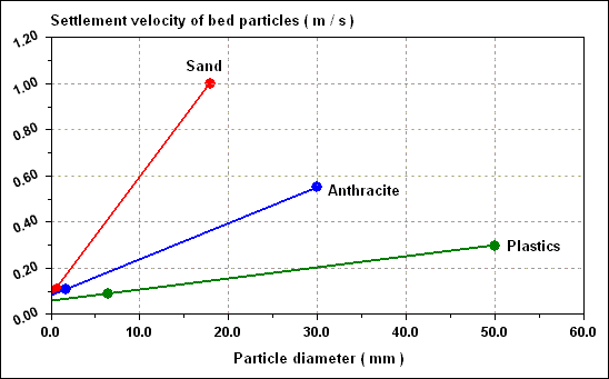
Typical settlement curves of sand of density 2,600 kg / m 3 ; anthracite of density 1,400 kg / m 3 and plastic of density 1,050 kg / m 3 are given in figure shown below.


Calculation :

Available anthracite has a grain size between 1.4 mm and 1.7 mm, i.e. a range of settling velocities ( assuming spherical particles ) of 0.11 to 0.09 m / s when NU is 1.2 x 10 - 6 m 2 / s. Plastic particles less than 6.5 mm diameter would have a settlement velocity less than the smallest anthracite particles. In practice, plastic media of 2.0 to 3.0 mm diameter having settlement velocities of 0.033 to 0.040 m / s would be suitable. Sand of greater than 0.65 mm diameter would have velocities greater than the largest anthracite grains, so sand of perhaps 0.7 to 0.9 mm diameter, with settlement velocities of 0.12 to 0.15 m / s would be satisfactory to form a lower bed. The situation would then be as in table given below.
Medium Material Density ( kg / m 3 ) Size range ( mm ) Settlement velocity ( m / s )
Upper Plastic 1,050 2.0 - 3.0 0.033 - 0.050
Middle Anthracite 1,400 1.4 - 1.7 0.09 - 0.11
Lower Sand 2,600 0.7 - 0.9 0.12 - 0.15

In practice, the anthracite would have a shape factor of perhaps 0.75 which would have a significant effect on the fall velocity.

5.5. Disinfection...

Many countries have water quality legislation which specifies limits on bacterial species such as Erischeria coliform and faecal coliform, ( commonly referred to as E.coli. and f.coli. ) in effluents discharged to receiving waters. Since domestic wastewaters commonly have 10 7 total coliforms / 100 mL, which is reduced by 99 % in conventional sewage treatment processes, the final effluent may still contain 10 5 total coliforms / 100 mL. Typical legislation for bathing waters would require ( after dilution ) less than 200 f.coli. / 100 mL in the median of multiple samples, this value being perhaps 1 / 3 to 1 / 6 of the total coliform count. Many of common tertiary treatment processes such as slow sand filters, rapid gravity filters, grass plots and clarifiers can remove large number of bacteria, removals of 40 - 70 % ; 87 - 97 % and 38 %, respectively.

Table of equations...


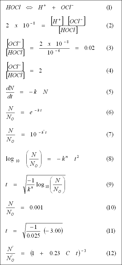
When the physical methods are insufficient it is common to use chlorine, or, less usually, ozone, as disinfecting agents. Chlorine reacts in water to produce hypochlorous acid which dissociates to give hypochlorite ions and protons, i.e. ;

Equation - 01

At 10 O C the dissociation constant is approximately 2 x 10 - 8 , i.e. ;

Equation - 02

where the brackets indicate concentrations in gramme ions or g molecules / L. Since pH = - log 10 [ H + ], the above relationship can be used to predict the ratio of hypochlorite ion ( OCl - ), to hypochlorous acid ( HOCl ) at any pH.


Example 5-5 :

Calculate the ratio of OCl - / HOCl in pure water at a temperature of 10 O C and pHs of 6, 8 and 10.

Calculation :

A pH of 6 means that [ H + ] = 10 - 6 g ions / L. Therefore ;

Equation - 03

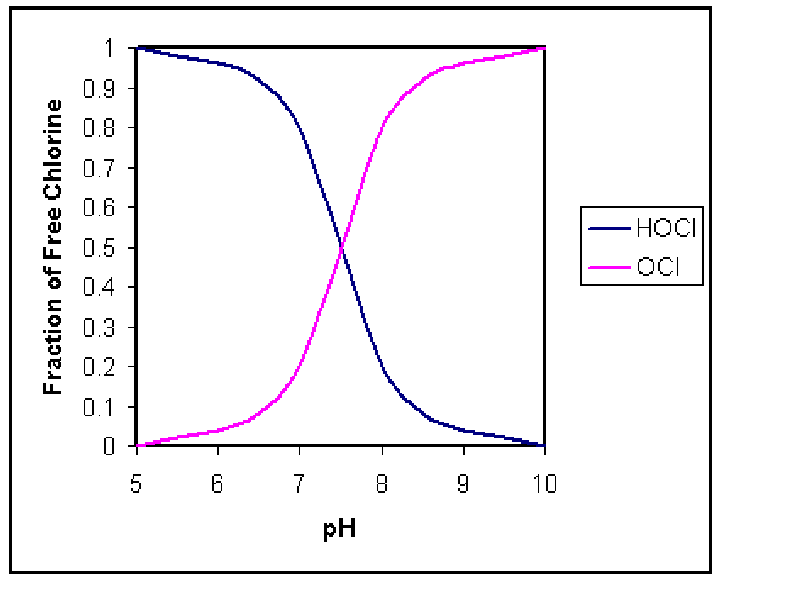
i.e. ( 0.02 / 1.02 ) ( 100 ) = or 2 % of the hypochlorous acid has dissociated. At pH 8 ;

Equation - 04

i.e. 67 % is as OCl - , and at pH 10, 99.5 % exists as OCl - . Several methods have been used to determine the rate of kill of bacteria by chlorine. The simplest is a first - order reaction, i.e. ;

Equation - 05

where N is the number of organisms at time t and k is a constant. Hence ;

Equation - 06

or ;

Equation - 07

where N O is the number when t = 0, and k ' is the constant k taken to base 10.

Chlorine reacts with organic compounds and with ammonia to produce a wide range of chlorinated organics together with mono -, di - and tri - chloramines ( NH 2 Cl, NHCl 2 and NCl 3 , respectively ). These are designated " combined " chlorine compounds to distinguish them from the " freely available " chlorine compounds ( HOCl and OCl - ). The term residual, e.g. " residual free chlorine ", refers to that remaining after initial oxidation reactions have taken place. A better fit to the experimental data is given by ;

Equation - 08

where k n is a constant which varies with concentration of the chlorine compound.

Example 5-6 :

In clear water at 0.1 mg / L of free residual chlorine the value of k n for E.coli. is 0.025 when t is in minutes. Calculate the contact time required to reduce the coliform concentration to 0.1 %.

Calculation :

From ;

Equation - 09

Equation - 10

Therefore ;

Equation - 11

thus t = 11 min.

An empirical equation has been derived for E.coli. which relates chlorine residual concentration ( mg / L ) to contact time for wastewaters ;

Equation - 12

The values of N ' and N O ' used are most probable numbers ( MPNs ) and represent a statistical value for the concentration of E.coli. determined by an MPN test.

Example 5-7 :

Determine the likely kill of E.coli. in a sewage effluent ( N O ' = 10 5 / 100 mL ) for a residual chlorine concentration of 2 mg / L and a contact time of 10 min.

Calculation :

N ' = ( N O ' ) [ 1 + ( 0.23 ) ( 2.0 ) ( 10 ) ] - 3

N ' = 5.7 x 10 2 / 100 mL

or 99.4 % kill.

For units treating less than 100 m 3 / h, common dosages and retention times are 10 mg / L of sodium hypochlorite solution ( as Cl 2 ) and 30 min, respectively.

5.6. Nutrient Removal...

The amount of nitrogen and phosphorus which is discharged in sewage can have a considerable effect on the growth of algae in lakes and receiving waters. One equation for algal growth is ;

106 CO 2 + 16 NO - 3 + HPO - 2 4 + 122 H 2 O + 18 H + ---- ( light and trace elements ) ----> C 106 H 263 O 110 N 16 P 1 ( algal synthesis ) + 138 O 2

Example 5-8 :

A population of 10,000 discharges 200 L / capita . day of effluent containing 15 mg / L N - NO 3 and 5 mg / L phosphorus. Calculate the total algal dry weight which could be produced per day, assuming 100 % efficiency of nutrient utilization.

Calculation :

From the formula C 106 H 263 O 110 N 16 P 1 the molecular weight is ;

( 12 ) ( 106 ) + ( 1 ) ( 263 ) + ( 16 ) ( 110 ) + ( 14 ) ( 16 ) + ( 31 ) ( 1 ) = 3,550

i.e. ( 16 ) ( 14 ) kg N or 224 kg N produces 3,550 kg algae and ( 1 ) ( 31 ) kg P or 31 kg P produces 3,550 kg algae. The population produces ( 10 4 ) ( 200 ) ( 15 x 10 - 6 ) kg N / day or 30 kg N / day and ( 10 4 ) ( 200 ) ( 5 x 10 - 6 ) kg P / day or 10 kg P / day. The N could produce ( 3,550 / 224 ) ( 30 ) = 475 kg algae / day, whereas the P could produce ( 3,550 / 31 ) ( 10 ) = 1,145 kg algae / day.

5.6.1. Nitrification...

Nitrogen may be removed in several ways ; one of the commonest being bacterial nitrification followed by bacterial denitrification. This effectively converts organic N eventually to N 2 gas ;


written using methanol as the carbon source. Nitrification step can be written as ;


Therefore 1 g of ammonia nitrogen requires ( 96 + 32 ) / ( 2 x 14 ) = 4.6 g O 2 .

In Chapter 4 it was shown that metabolization of 1 kg BOD 5 / day required an input of approximately 1.2 kg O 2 / day in the activated sludge plant operating under conventional conditions. For an extended aeration plant operating under a low FMR loading ( typically < 0.10 / day ) there will be a considerable additional oxygen requirement for the nitrification step.

Example 5-9 :

Analysis of raw sewage showed 40 mg / L organic and ammonia nitrogen associated with 200 mg / L BOD 5 . Assuming 100 % of the nitrogen is oxidized to NO 3 - in an extended aeration plant, calculate the O 2 requirement expressed per kg BOD 5 / day, given that 1 kg BOD 5 requires 1.2 kg oxygen.

Calculation :

200 mg BOD 5 from above requires ( 200 x 10 - 6 ) ( 1.2 ) = 2.4 x 10 - 4 kg O 2 . Conversion of 40 mg NH 3 - N to NO 3 - requires ( 4.6 ) ( 40 x 10 - 6 ) = 1.8 x 10 - 4 kg O 2 . Thus, in total, 200 mg BOD 5 plus the associated organic nitrogen requires 4.2 x 10 - 4 kg O 2 . Therefore 1 kg BOD 5 plus the associated organic nitrogen together would require ( 4.2 x 10 - 4 kg O 2 ) / ( 200 x 10 - 6 kg BOD 5 ) = 2.1 kg O 2 / kg BOD 5 . In practice, a value of 2.0 - 2.5 kg O 2 / kg BOD 5 is used for extended aeration plants.

5.6.2. Nitrification Kinetics...

Considering the activated sludge system in figure given below, for a reactor volume V L ( m 3 ), inflow and waste sludge flow F and F W , respectively ( m 3 / day ), the rate of increase in nitrifying organism concentrations X N ( mg / L ) is given in terms of the specific growth rate ( N ) ( MU ) and the decay rate constant ( N ) ( K D ) ( both referring to nitrifying organisms ) as ;


[ ( dX N / dt ) ( V L ) ] = [ ( N ) ( MU ) - ( N ) ( K D ) ] ( V L ) ( X N ) - ( F W ) ( X N - W ) - ( F - F W ) ( X N - E )

where ; X N - E and X N - W : effluent and sludge waste stream concentrations of nitrifying organisms. For the organisms to increase ;

( N ) ( MU ) - ( N ) ( K D ) >= [ ( F W ) ( X N - W ) + ( F - F W ) ( X N - E ) ] / [ ( V L ) ( X N ) ]

i.e. ;

1 / mean cell residence time

or ;

( N ) ( MU ) - ( N ) ( K D ) >= 1 / THETA C

since ;

[ ( F W ) ( X N - W ) ] / [ ( V L ) ( X N ) ]

can be assumed to be the same as ;

[ ( F W ) ( X W ) + ( F - F W ) ( X E ) ] / [ ( V L ) ( X ) ]

where ; X W , X E and X : waste sludge, effluent and reactor concentration of sludge solids. The expression [ ( V L ) ( X ) ] / [ ( F W ) ( X W ) + ( F - F W ) ( X E ) ] is defined as 1 / THETA C where THETA C is the sludge retention time or sludge age.

( N ) ( MU ) - ( N ) ( K D ) may be written as the net specific growth rate for nitrifying organisms ( N ) ( MU N ). Since ( N ) ( MU ) has a maximum value for the NO 2 - ----> NO 3 - reaction carried out by nitrobacter organisms of < 0.14 1 / day it is likely that a realistic value for ( N ) ( MU N ) of less than 0.1 1 / day is achieved in practice. Thus the sludge age would have to be >= 10 days to allow nitrifying organisms to increase. Conditions which are conducive to high nitrification in the activated sludge process include ;

( a ) DO concentration >= 2 mg / L
( b ) THETA C >= 20 days
( c ) FMR < 0.1 kg BOD 5 / kg MLSS . day
( d ) MLSS > 3,000 mg / L

Example 5-10 :

A small unit treating the waste from 250 persons producing 200 L / capita . day and 0.5 kg BOD / capita . day is 3 m deep. Calculate the air required per kg BOD, the aeration volume and the daily sludge wastage rate. The MLSS is to be 4,000 mg / L, the settled sludge return is at 10,000 mg / L and THETA C = 20 days.

Calculation :

Since nitrification is intended, a minimum of 2 kg O 2 / kg BOD is required. A 3 m deep tank would probably give an oxygen transfer efficiency of approximately 4 %. Therefore ;

( 2,000 / 32 ) ( 22.4 / 0.04 ) ( 10 - 3 / 0.21 ) = 167 m 3 air / kg BOD is required, assuming 22.4 L air at NTP contains ( 0.21 ) ( 32 g O 2 ), the total air requirement is therefore ;

( 250 ) ( 0.05 ) ( 167 ) = 2,090 m 3 / day

Assume the FMR is to be 0.05 kg BOD 5 / kg MLSS . day ;

MLSS = [ ( 0.05 ) ( 250 ) ] / ( 0.05 ) = 250 kg MLSS

At an average MLSS concentration of 4,000 mg / L in the aeration tank this gives a volume requirement of ( 250 / 0.004 ) ( 10 - 3 ) = 62.5 m 3 aeration capacity. Since THETA C is to be 20 days, the sludge wasted / day should be 1 / 20 the total sludge in the reactor. However, an inadvertent waste of MLSS occurs in the effluent. If this is estimated as 20 mg / L dry SS the mass of SS lost per day is ( 20 x 10 - 6 ) ( 250 ) ( 200 ) = 1 kg MLSS / day if the value of F is assumed to be very large compared with F W . The sludge wastage rate in the waste stream should therefore be ;

( 250 / 20 ) - 1 = 11.5 kg MLSS / day

If this is removed from the secondary settlement tank, in order to keep the volume to a minimum, then the volume to be wasted, assuming a settled sludge concentration of 10,000 mg / L, is ;

( 11.5 ) / ( 10,000 x 10 - 6 ) = 1.15 x 10 3 L / day = 1.15 m 3 / day.

5.6.3. Alkalinity Changes in Nitrification and Denitrification...

From the equations for nitrification and denitrification it can be seen that the nitrification stage produces acidity as H + ions, and the denitrification stage produces alkalinity as OH - ions. The alkalinity of waters is usually referred to in terms of mg / L of CaCO 3 equivalent. Thus for the nitrification step ;

N ----> NO 3 - + 2 H +

14 g -------------- 2 g H +

Now 2 g H + is equivalent to 100 g of CaCO 3 since we can write a reaction such as ;

2 HCl + CaCO 3 ----> CaCl 2 + CO 2 + H 2 O

2 g H + + 100 g CaCO 3

Thus 1 g N which is oxidized reduces the alkalinity by ( 100 ) / ( 14 ) = 7.1 g CaCO 3 . For the denitrification step ;

NO 3 - ----> N + OH -

and since 17 g OH - = 1 g H + = 50 g CaCO 3 , then denitrification of 1 g of N as NO 3 - produces 3.6 g of alkalinity expressed as CaCO 3 . Since waters in many parts of the world have low alkalinity, there is a danger that the alkalinity may be removed by nitrification and the pH will drop below the point where bacteria cease to be operative.

Example 5-11 :

A wastewater plant is operated in a nitrifying phase in order to convert 40 mg / L of oxidizable N to NO 3 - . If the water contains only 200 mg / L of alkalinity ( as CaCO 3 ) calculate the amount of lime which must be added per litre if a minimum alkalinity of 100 mg / L ( as CaCO 3 ) is to remain at all times.

Calculation :

1 mg / L oxidizable N uses up 7.1 mg / L CaCO 3 . Hence 40 mg / L would require 284 mg / L CaCO 3 . Allowing for the safety factor of 100 mg / L CaCO 3 residual, a concentration of 184 mg / L CaCO 3 alkalinity is needed.

100 mg / L CaCO 3 = 76 mg / L Ca( OH ) 2 ( slaked lime )

i.e. ( 184 ) ( 76 / 100 ) = 140 mg of slaked lime would be required per litre of wastewater.

5.6.4. Single Vessel Nitrification and Denitrification...

For more info about this sub-section you can reach these links located in the "TOPRAK HOMEPAGE"...


Moreover please return to the :

"START PAGE"

to search the site by using "FREE FIND" window...