Chemical Treatment - 11...
Chapter 11 - Pre - Treatment Requirements...
11-1. Introduction...
Prior to the precipitation process, waste streams may require pre-treatment steps consisting of the following : flow
equalization, neutralization, or treatment of individual waste streams prior to combination with other waste streams.
Oil removal, chromium reduction, and cyanide destruction are examples of other pre-treatment steps.
11-2. Flow Equalization...
To prevent flow rate, temperature, and contaminant concentrations from varying widely, flow equalization is often used. For
all methods of flow equalization, the designer has to be sure that the flow rate, temperature, and contaminant concentration
of the influent are well characterized so that flow rates and concentrations that would overload the system are avoided. In
addition, the designer has to be sure that the system is flexible enough that it could be moved or expanded in the future,
or that the flow rate could be changed. There are four commonly used flow equalization techniques :
• Alternating flow diversion.
• Intermittent flow diversion.
• Completely mixed combined flow.
• Completely mixed fixed flow.
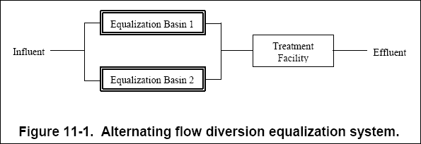
( a ) In the alternating flow diversion, shown in Figure 11-1, one equalization basin is designed to collect the total flow
of the influent for a given time while a second basin is discharging. For successive periods, the basins alternate between
filling and discharging. Mixing is typically maintained so that the pollutant levels in the discharge remain constant with
relatively constant flow. This type of system can provide a large degree of equalization; however, the disadvantage is that
the cost of constructing a second basin is high (Water Environment Federation, 1994).

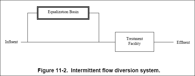
( b ) The intermittent flow diversion system, shown in Figure 11-2, allows the waste stream to be diverted to an
equalization basin for short periods. The diverted flow is then metered back into the main stream at a controlled rate.
The volume and variance of the pollutants in the diverted water will dictate the rate at which the diverted flow is fed
back into the main stream.

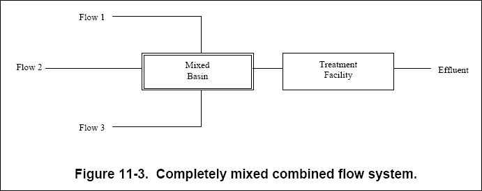
( c ) The completely mixed combined flow system, shown in Figure 11-3, is designed to provide complete mixing of multiple
flows (or wells) at the front end of the treatment facility. By thoroughly mixing multiple flows, this type of system can
reduce variance in each stream. This system should only be used when flows are compatible and can be combined without
creating additional problems.

( d ) The completely mixed fixed flow system, shown in Figure 11-4, is designed to completely mix waste streams in a large
holding basin directly before the treatment facility. This system levels variations in influent stream parameters and
provides constant discharge.

( e ) Mixing within an equalization basin is a necessity. The waste stream can be mixed through baffling, through
mechanical means, and through aeration. Mixing power levels vary with basin geometry; however, as a general rule,
0.3 L / m 3 . s (18 cfm / 1,000 ft 3 ) of basin volume is the minimum required to keep light
solids in suspension (approximately 0.02 kW / m 3 (0.1 hp / 1,000 gal).
( f ) Baffling, although not a true form of mixing and less efficient than other mixing methods, prevents short-circuiting
and is typically the most economical. Over-and-under or around-theend baffles may be used. In wide equalization tanks,
over-and-under baffles are preferable because they provide more efficient horizontal and vertical distribution. To prevent
suspended solids in the wastewater from settling and remaining on the bottom, the influent should be introduced at the
tank bottom. Typically, baffling is not advisable as a proper way of mixing wastewaters that have high concentrations of
settable solids (Water Environment Federation, 1994).
( g ) Owing to its higher efficiencies, mechanical mixing is typically recommended for smaller equalization tanks,
wastewater with higher suspended solid concentrations, and waste streams in which waste strength frequently fluctuates.
Mechanical mixers are typically selected on the basis of manufacturer’s data or laboratory pilot tests. Geometrical
similarity should be preserved and the power input per unit volume should be maintained if pilot plant results are to be
used at full scale. Vortexes should be avoided, which reduces wasted power, by mounting the mixer off center or at a
vertical angle or by extending the baffles out from the wall.
( h ) Mixing by aeration is the most energy intensive method. Aeration, in addition to mixing, chemically oxidizes reducing
compounds, as well as physically stripping volatile organic compounds (VOCs). The designer should note that some states
require air discharge permits for VOC emissions to the atmosphere or that the equalization tank be classified as a process
tank. Equalization tanks should be sloped to drains and be provided with a water supply for flushing, otherwise odor and
health nuisances may occur after the tank is drained.
( i ) Design of equalization facilities begin with detailed pre-design studies, which include gathering data on flow and
all pollutants of consequence. Many references outline design procedures for the equalization techniques described above.
Suggested references are Water Environment Federation (1994), EPA (1987), and Water Environment Federation (1991).
11-3. Oil and Grease Removal...
Oil and grease in solution can inhibit the settling of precipitates by creating emulsions. Oil droplets suspended in water
tend to suspend particles, such as metal precipitates, that would otherwise settle out of solution. Oil and grease can be
removed through emulsion breaking, dissolved air flotation, skimming, or coalescing. Specialty chemicals such as cationic
polymers and emulsion breakers can help provide this treatment step.
11-4. Chromium Reduction...
Hexavalent chromium must be reduced to the trivalent form prior to hydroxide precipitation. If sulfide precipitation is
used, this reduction, or pre-treatment, is not necessary. Reduction typically occurs at pH 2.0 to 3.0 through adding acid
and a reducing agent (e.g., sulfur dioxide, ferrous sulfate, sodium metabisulfite, or sodium bisulfite). An oxidation-reduction potential (ORP) meter can be used to monitor the reaction, notifying operators when it is complete.
The ORP reading may vary with wastewater characteristics. A color change from yellow to green is typically evident.
Suggested references are available describing this process are EPA (1987) and the Naval Civil Engineering Laboratory (1984).
11-5. Cyanide Destruction...
Destroying cyanide (CN – ) is an important pre-treatment step before metals are removed because cyanide forms
complexes with metals and prevents them from precipitating as hydroxides. However, once the cyanide–metal bond is broken,
the metal is free to precipitate under the appropriate pH conditions.
( a ) Because stable organo-metallic complexes may form or toxic hydrogen cyanide gas may evolve, cyanide wastes should
not be mixed with metal-containing wastes. Aquatic life can be destroyed when cyanides are discharged into surface waters.
Free cyanides, hydrogen cyanide, and the cyanide ions are the most toxic forms of cyanides in the environment. The
threshold toxicity limit for free cyanide in well-oxygenated waters is approximately 0.05 mg/L. For metalcyano complexes,
the threshold toxicity limits are in the range of 0.1 to 1.0 mg/L. In addition, cyanate, an oxidation product of cyanide
ions, is also toxic with a threshold toxicity limit as low as 75 mg/L.
( b ) A two-step process is typically used to destroy cyanide. In the first step, cyanide is converted to cyanate using
sodium hypochlorite at pH 10 or greater. This first step typically requires 30 minutes. The reaction endpoint may be
monitored with an ORP meter or by a visual color change in solution, from green to blue. In the second step, cyanate is
converted to carbon dioxide and nitrogen. This is done by decreasing the pH with acid to 8.5. The second step requires
approximately 10 minutes. In operation, feedback ORP and pH meters may control the reactions.
( c ) Common technologies available for treatment of cyanides are chemical oxidation, electrolytic oxidation, and
electrodialysis. Suggested references are Naval Civil Engineering Laboratory (1984) and EPA (1987).
11-6. Chelating/Complexing Agent Removal...
Established methods exist to remove chelating/complexing agents. Chemical methods include using starch xanthate, ferrous
sulfate, waste acids, sulfide ions, sodium hydrosulfite, and high pH lime (EPA, 1987). A common industry practice is to use
a combination waste treatment method using acid and high pH lime. This process first adjusts the pH of the organo-metallic
waste to approximately 2 with dilute acid (sulfuric, nitric, or hydrochloric). After the chelate/complex breaking step, the
pH is then raised to 9.5–11 to form insoluble metal hydroxides (EPA, 1987). Chemical oxidation using potassium permanganate
(KMnO 4 ), I ozone, chlorine dioxide, or hydrogen peroxide (H 2 0 2 ) has also been
used to "break" metal-complexes and metal-chelates to precipitate the metal ions.


