Chemical Treatment - 12...
Chapter 12 - Equipment Requirements...
12-1. Introduction...
P/C/F systems generally consist of the following equipment :
Equalization basin.
pH control system, including pH/ORP sensors, analyzers and recorders.
Precipitation tanks and reactors.
Chemical feed apparatus.
Mixers and flocculators (or agitators).
Clarifiers, including thickener.
Sludge dewatering equipment.
Ancillary or miscellaneous equipment.
( a ) The designer should note that numerous vendors offer pre-packaged P/C/F systems. Prepackaged systems are typically
mounted on skids and usually contain all necessary equipment, including a pH control system, an oxidation/reduction system
(if required), reaction tanks, mixers, clarifier, sludge dewatering device, and an effluent holding tank. Pre-packaged
plants are available with flow rates typically ranging from 0.63 L/s (10 gpm) to 93 L/s (1500 gpm). Pre-packaged systems
typically do not include equalization; however, this can be added as ancillary equipment. Skids, for pre-packaged systems,
are typically up to 6 m (20 ft) long and 1.5 to 2.4 m (5 to 8 ft) wide (NEESA, 1993). For a design flow rate of
0.8 m 3 / min (20 gpm), approximately 37 m 2 (400 ft 2 ) of skid space is required,
whereas a 65-gpm system requires approximately 92 m 2 (1,000 ft 2 ) of skid space (NEESA, 1993).
Package systems usually include plumbing and electrical wiring adequate for connection to on-site water and power supplies.
A 480-V, 3-phase power supply is typically required.
( b ) The designer should note that individual components can become very large at higher design rates (especially if
certain reagents, such as carbonate precipitating agents, are used). Consider the following example where hydroxide
precipitation is used for a 100-gpm operation. For this example tankage requirements would include ;
A 45-m 3 (12,000-gal.) (2-hour retention time) equalization tank.
A 23-m 3 (6,000-gal.) mixing tank.
A 76-m 3 (20,000-gal.) clarifier.
A 3-m 3 (800-gal.) thickener tank (NEESA, 1993).
Should design flow rates call for tanks in excess of 150 m 3 (40,000 gal.), field erection is usually
necessary. In some cases, this can increase construction time by several months.
12-2. Equalization Tanks / Systems...
See Paragraph 11-2.
12-3. pH Control System...
The pH scale corresponds to hydrogen ion concentrations from 100 to 1014 moles per liter and, therefore, systems for pH
control cover an extreme range. No other common measurement covers such a tremendous range. In addition, the measuring
electrodes can respond to changes as small as 0.001 pH, and, therefore, systems for pH control are also extremely
sensitive. The design of these pH control systems is complicated by pH being a logarithmic function of concentration. For
example, if a certain amount of base added to a solution of strong acid would increase the pH from 2 to 3, increasing the
pH further to 4 may only require 10% of the original volume. If it is necessary to increase the pH to 5, only 1% of the
original volume is required, and for pH 6, only about 0.1%. Therefore, taking a waste stream from pH 2 to 7 can be a
difficult control problem.
( a ) The pH control system typically has the following equipment :
pH sensor.
Analyzer.
Recorder.
In addition, there is typically a control panel with an indicator, starters, and controls for chemical metering pumps,
high/low pH alarms, switches, and mixer motor starters.
( 1 ) pH/ORP Sensors. A pH sensor is an electrochemical device that produces a voltage proportional to the pH/ORP of the
solution into which it is placed. ORP probes are used when agents other than hydroxide precipitating agents are used. The
following things should be done when selecting the proper pH/ORP sensors :
Determine mounting requirements and sensor body style.
Ensure that the measuring electrode fits process temperature, chemistry, and physical parameters.
Determine if an automatic temperature compensator is required (becomes critical as the temperature changes from
25 O C, or the pH from 7.0).
Determine what accessory hardware is required to mount a particular type of sensor.
Determine cabling requirements to connect the sensor to the analyzer.
ORP displays should be capable of reading both positive and negative millivolt values.
( 2 ) pH Analyzers. The key function of the pH analyzer is to receive the voltage signal from the pH sensor and convert it
to a pH value. The pH scale has an equivalent y mV scale. The mV scale ranges from +420 to 420. At a pH of 7.0 the mV
value is zero. Each pH unit change corresponds to a change of + or 60 mV. As the pH becomes more acidic, the values become
greater.
For most processes, a pH analyzer is required to do more than simply display a pH value. Based on specific pH setpoints,
the analyzer also transmits signals to recorders or control systems that activate (or deactivate) alarms, valves, or pumps.
( b ) For batch systems, the pH control device can be relatively simple with only onoff control provided via a solenoid or
air-activated valves. For continuous flow systems, pH control is more complicated because of the greater potential for
fluctuation in both flow and contaminant concentration. Continuous flow pH control systems are called proportional, cascade,
feed-forward, or feedback pH control.
( c ) Many industrial instrumentation controllers and analyzers, because microprocessor-based technology has been
introduced, now use configurable algorithms to characterize their function curves. The segmented function curves, generated
by these algorithms, are inversely proportional to the titration curve for the influent wastewater and the selected
neutralizing (or precipitating) agent. This results in a near-linear controller output with respect to reagent demand. For
pH values between 4 and 10 (most common for ground water remediation projects), a single characterized curve typically will
be sufficient for pH control. If the control detects a pH outside of this range, an alternate curve can be developed and
electronically switched to replace the normal curve.
( d ) Suggested references for further reading for design of pH control are Water Environment Federation (1994, 1993), Hoyle
(1976), Cushnie (1984), and Hoffman (1972).
12-4. Tanks / Reactors...
Precipitation tanks (or reactors) are built from a wide range of construction materials, such as masonry, plastic, metal,
fiberglass, or elastomers. Coatings and liners may be used to prevent corrosion and premature decomposition of the tank
walls. For example, concrete reactors susceptible to corrosion can be installed with a multi-layered coating of
glassreinforced epoxy polyamide covered by a coating of polyurethane elastomer to extend the service life (EPA, 1987).
( a ) Precipitation reactors are typically cubical or cylindrical. Cubical tanks typically do not need baffling, whereas
cylindrical tanks are typically constructed with "ribs" that prevent swirling and maintain adequate contact between the
reactants. A general rule-of-thumb is that the depth of the liquid should be roughly equivalent to the tank diameter or
width. Reactor sizing is based on flow rate and retention time required to complete chemical reactions. Carbonate reagents,
as discussed earlier, generally require longer retention times, thus larger reactors.
( b ) Reactors can operate in either batch or continuous modes, and can be configured as either single-or multi-stage
tanks. Multi-stage, continuous setups are generally required to neutralize and precipitate concentrated wastes with various
feed rates (EPA, 1987). In these units, most of the chemical reagent is used in the first reactor, with only final pH
adjustments (polishing) made in the remaining reactor or reactors. This is particularly true when using reagents that
require extensive reaction times. The batch or single-stage continuous precipitation setup is most suitable for use with
highly buffered solutions, dilute wastewaters not subject to rapid pH or flow rate changes, or small, inconsistent flows.
12-5. Rapid Mixers...
The most common type of mixing device used for wastewater treatment (including P/C/F system) is the rotating propeller
mixer. Impeller mixers are classified into three groups :
Paddles.
Turbines.
Propellers.
Of these, only turbine and propeller mixers are used for rapid mixing.
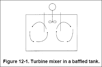
( a ) Turbine Mixers. Figure 12-1 shows a typical turbine mixer. Generally, turbine mixers resemble multibladed paddle
mixers with short blades turning at high speeds on a shaft typically located near the center of the mixing chamber. The
impeller may be shrouded, semi enclosed, or open. The diameter of the impeller is typically 30 to 50% of the diameter of
the mixing vessel. Turbine mixers, especially in thin liquids, impart strong currents that persist throughout the vessel.
Baffles or diffuser rings must often be used to prevent vortexes. Turbine mixers are typically mounted vertically and in
the center of the mixing chamber, 50 to 100% of a diameter above the chamber floor.

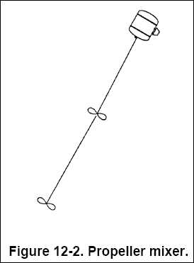
( b ) Propeller Mixers. Figure 12-2 shows a typical propeller mixer. These mixers have high speed, low impellers and are
generally used for thicker solutions. At full motor speed, small propeller mixers revolve at about 1,750 rpm, whereas
larger mixers turn at 400800 rpm. Typically, propeller mixers are much smaller in diameter than either paddle or turbine
mixers, rarely exceeding 0.46 m (18 in.) in diameter, regardless of the size of the mixing vessel. Deep mixing vessels
typically require two or more propellers on the same shaft. Where top entry is required for a propeller mixer, the mixer
is mounted angled and off-center. Flow should parallel the long axis of the basin. For small, open tanks of less than
3,800 L (1,000 gal.) capacity, top-entry mixers are best. In this case either an angle-mounted propeller mixer or a
vertically mounted turbine mixer is typically satisfactory. For nonstandard tank geometry and larger tanks, side-entering
mixers are generally used.

( c ) Other Rapid Mixing Methods. Although mechanical mixing is the most common, a waste stream can be rapidly mixed
through :
Baffled channels.
Hydraulic jump mixers.
Pneumatic mixing through compressed air injection.
In-line static mixers.
Baffled channels and pneumatic mixing are techniques better suited for flocculation than rapid mixing. In-line static
mixers are commonly used for rapid mixing; however, they possess two distinct disadvantages: high head loss (up to 0. 9 m
[3 ft]) and the mean velocity gradient G, cannot be changed to meet varying requirements.
( d ) Suggested Rapid Mixing References. These are EPA (625/1-75-003a, 430/9-79-018), EPA (1987), and TM 5-814-3.
12-6. Flocculators/Agitators...
The two most commonly used mechanical flocculators for slow
mixing are the paddle type and the reel type. For the removal of heavy metal contaminants, flocculator/clarifiers come in
three basic types :
Basic settling chambers.
Mixer clarifiers.
Inclined plate clarifiers.
Of the three types, inclined plate clarifiers are the most commonly used and will be discussed in more detail.
( a ) Basic settling chambers. Feed is distributed at one end and overflows at the other. This type of unit usually
requires a mixing zone to flocculate the particles before clarification. Rectangular or circular shaped units are
available with either flat or conical bottoms. Numerous references are available in the literature.
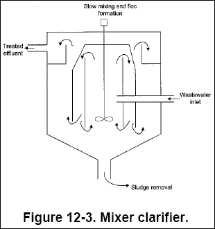
( b ) Reactor Clarifiers. A reactor clarifier is a sludge blanket unit that combines coagulation, flocculation, and
settling in a single unit. Colloidal destabilization (coagulation) may be less effective than a conventional settling
chamber; however, there are distinct advantages in recycling preformed floc. By seeding the influent wastewater with
previously formed floc or by recycling a portion of the precipitated sludge, it is possible to reduce both coagulant
dosage and the time of floc formation. The sludge blanket serves as a filter for improved effluent clarity. A reactor
clarifier is shown in Figure 12-3.

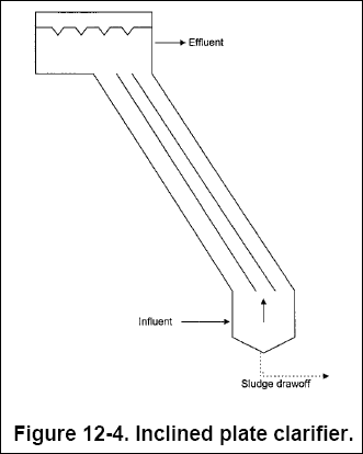
( c ) Inclined Plate Clarifier. A plate settler is a deep, rectangular unit equipped with parallel plates slanted at an
angle (typically 45 or 55 O ) and spaced 25 to 50 mm (1 to 2 in.) apart. Figure 12-4 shows a schematic of a
plate settler. Most common materials of construction include 0.635-cm (1/4-in.) thick ASTM A36 structural quality carbon
steel, or 304 and 316 stainless steel. Interior carbon surfaces are typically coated with epoxy.

( 1 ) By the use of parallel plates, a large settling area can be incorporated into a relatively small space. Plate
settlers often require only a quarter of the floor space of conventional clarifiers (EPA, 1987). In buildings where
ceiling height is limited, the use of plate settlers can become a major benefit.
( 2 ) Because of its overall smaller size, the unit can be manufactured elsewhere and delivered to the construction site
for installation.
( 3 ) After the flocculation process is complete, the wastewater flows upward through the plates. Floc particles settle
onto the plates and slide into the sludge-holding area of the unit. The sludge compartment typically has pitched sides,
access hatches, and a mechanical thickening device. Through the use of inclined plates, floc particles have a shorter
distance over which to settle, and an effective laminar flow condition is easier to attain, thereby facilitating the
settling process (Water Environment Federation, 1994).
( 4 ) The plate settler plate packs typically consist of smooth-surfaced polypropylene plates assembled into packs.
Typical construction uses stainless steel rods and PVC spacers to "lock" the plates in at the proper angle. Plate packs
are typically equipped with lifting eyes.
( 5 ) Plate settlers are available in models ranging from 5.1 m 2 (55 ft 2 ) to
204.5 m 2 (2,200 ft 2 ). A typical maximum recommended loading rate for metal hydroxides is
approximately 0.25 gpm / ft 2 .
( 6 ) The designer should be aware that under contaminant-heavy loadings, operational problems can develop, causing solids
to "bridge" in the sludge-holding area, making their subsequent removal difficult. Excessive polymer addition can further
compound the problem.
12-7. Chemical Feed Equipment...
As discussed earlier, chemical feed equipment consists of chemical storage tanks, agitation, level instrumentation,
dissolving tanks, gravimetric or volumetric feeders, metering pumps, and slaking and slurrying equipment. Storage tanks
should be sized according to maximum anticipated feed rate, shipping time required, and quantity of shipment. The total
storage capacity should be more than sufficient to guarantee a chemical supply while awaiting delivery. Storage containers
should be compatible with the reagent being used. High calcium quicklime, for example, is hygroscopic, and therefore must
be stored in moisture-proof tanks to prevent atmospheric degradation. Suggested chemical feed system references are EPA
(430/9-79-18) and CEGS 11242.
12-8. Sludge Dewatering Equipment...
( a ) The slurry of thickened precipitate is typically dewatered to increase the solids content, prior to disposal.
Commonly used dewatering techniques are :
Vacuum filtration.
Filter press.
Belt press.
Of the three listed dewatering techniques, plate and frame filter presses are the most commonly used for HTRW site
remediations. Numerous references are available in the literature. A couple of suggested references are CEGS 11360, Plate
and Frame Filter Press System, and Water Environment Federation (1991).
( b ) Typically, recovery and reuse of metals separated from the sludge does not prove economical. This is attributable to
the low commercial value of the metals normally found in ground water (e.g., iron and manganese) and the costs associated
with separating these metals from the sludge (and from the other metals in the sludge).
12-9. Miscellaneous Equipment...
Miscellaneous equipment requirements include flow monitoring and effluent pH recording equipment necessary to prevent
discharge of insufficiently treated waste. It also includes electrical and mechanical fit-up as well as spare parts such
as pH probes, pH controller circuit board, metering pump ball valves, o-rings, etc., to prevent any excessive downtime
(EPA, 1987).


