Sedimentation...

General Considerations...

In sedimentation, settling tanks are used for removing settleable solids and.for reducing the suspended solids content in wastewater. Selection of sedimentation depends on plant size, the nature of the wastewater to be treated, and effluent requirements.

Functions and Types of Sedimentation Units...

In most facilities, primary sedimentation is currently used as a preliminary step ahead of biological treatment. Sedimentation tanks are designed to operate continuously. They are usually rectangular or circular and have hoppers for sludge collection. Most sedimentation tanks are constructed with gently sloped bottoms and have sludge hoppers with relatively steep sides. Non-mechanized settling tanks are used only in very small installations ; the sludge moves to hoppers by gravity where it is removed.

( a ) Design of primary sedimentation tanks. The function of primary sedimentation is to reduce the load on the biological treatment units. Efficiently designed and operated primary sedimentation tanks should remove 50 to 65 percent of the suspended solids and 25 to 40 percent of the BOD.

( b ) Secondary sedimentation tanks for activated sludge plants. The function of the activated sludge settling tanks is to separate the activated-sludge solids from the mixed liquor. It is the final treatment step in the secondary treatment process. The effluent from the final sedimentation tank should be well-clarified, stable effluent low in BOD and suspended solids.

( c ) Secondary sedimentation tanks for trickling filter plants. The function of these settling tanks is to produce a clarified effluent. On Army installations, it is common practice to recirculate the settled sludge to the primary sedimentation basin or the trickling filter.

Design Parameters...

( a ) Primary settling tanks. The tanks will be designed for the average daily flow or daily flow equivalent to the peak hourly flow that requires the largest surface area. Surface loading rates for primary settling tanks are given in Table 1. All tank piping, channels, inlets, outlets, and weirs will be designed to accommodate peak flows. Use 3.0 times average hourly flow if specific peak flows are not documented. Facility designs will normally include two tanks. Each tank will be sized, as a maximum, for 50 percent of the plant design flow.

Table 1. Surface loading rates for primary settling tanks.

Plant design flow ( mgd ) Surface loading rate 1 ( gpd / square foot )
Average flow Peak flow
0 - 0.01 300 500
0.01 - 0.10 500 800
0.10 - 1.00 600 1,000
1.00 - 10.00 800 1,200
Above 10.00 1,000 1,200
1 : These rates must be based on the effective areas (Figures 1 and 2).

( b ) Secondary sedimentation tanks. The sedimentation tanks should be designed for the flow (average or peak) that requires the largest surface area. Surface loading rates for secondary settling tanks are given in Table 2. Similar to primary tanks, the facility designs will normally include two tanks, each handling 50 percent of the design flow.

Table 2. Surface loading rates for secondary settling tanks.

Plant design flow ( mgd ) Surface loading rate 1 ( gpd / square foot )
Average flow Peak flow
0 - 0.01 100 200
0.01 - 0.10 300 500
0.10 - 1.00 400 600
1.00 - 10.00 500 700
Above 10.00 600 800
1 : These rates must be based on the effective areas (Figures 1 and 2).

( c ) General design considerations for all clarifiers.

( 1 ) Detention period. Detention time is commonly specified as 2.5 hours for primary tanks serving all types of plants, except when preceding an activated sludge system, where detention time is specified as 1.5 hours. Selection of optimum detention time will depend on the tank depth and the overflow rate. For those Army installations where the contributing population is largely nonresident, the detention period to be used in design of primary settling tanks is 2 hours, based on the average hourly rate for the 8-hour period when the maximum number of personnel will be contributing to sewage flow.
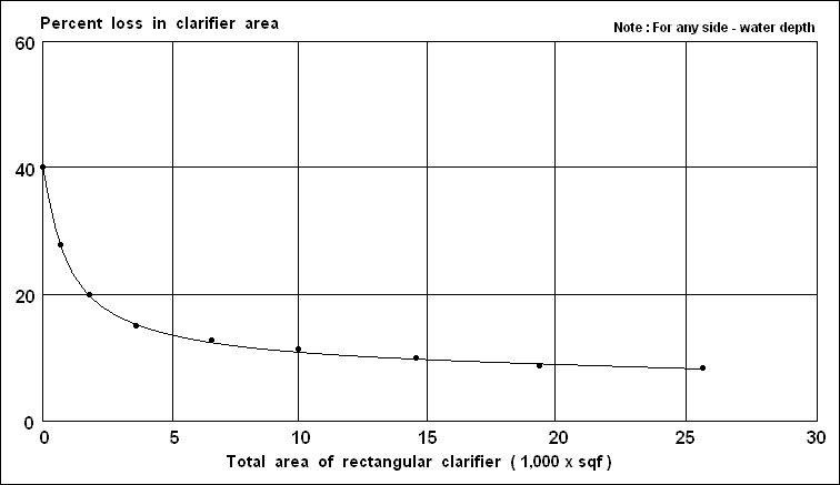


Figure 1. Effective surface area adjustments for inlet - outlet losses in rectangular clarifiers, L : W = 4.
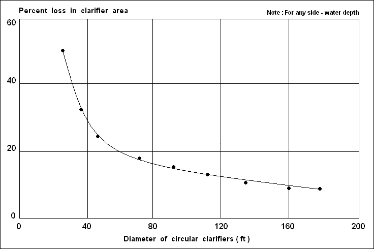


Figure 2. Effective surface area adjustments for inlet - outlet losses in circular clarifiers.

( 2 ) Weir rate. The overflow loading on weirs will not exceed 5,000 gpd per lineal foot for plants designed for less than 0.1 mgd, or 10,000 gpd per lineal foot for plants designed between 0.1 and 1.0 mgd. Weir loading for plants designed for flows of more than 1.0 mgd may be higher, but must not exceed 12,000 gpd per lineal foot. When pumping is required, the pump capacity will be related to tank design to avoid excessive weir loadings.

Tank Types and Design Features...

( a ) General features. Inlets to a settling tank will be designed to dissipate the inlet velocity, to distribute the flow uniformly, and to prevent short-circuiting. The inlet and outlet channels will be designed for a minimum velocity of 2 fps at the average flow rate and will have corners filleted to prevent deposition and collection of solids. Tanks can be circular or rectangular. Side water depths should be a minimum of 6 feet and a maximum of 10 feet. A 2 to 4 foot additional depth should be provided for the sludge blanket. Limit the use of circular clarifiers to applications greater than 25 foot diameter. Where space permits, at least two units will be provided.

( b ) Rectangular tanks. The minimum length of flow from inlet to outlet of a rectangular tank will be 10 feet in order to prevent short-circuiting of flow in the tank. Tank length-to-width ratio should vary between 3 : 1 and 5 : 1. Tanks will be designed with a minimum side water depth of 7 feet, except final tanks in activated sludge plants, which will be designed with a 9-foot minimum depth.

( 1 ) Inlets and outlets. Inlets to rectangular tanks will be designed so as to prevent channeling of wastewater in the tank. Submerged ports, uniformly spaced in the inlet channel, are an effective means of securing distribution without deposition or channeling. Outlet overflow weirs used in rectangular tanks will be of the adjustable type, and serrated weirs are preferred over straight ones. Overflow weirs will be used in most cases.

( 2 ) Collection and removal of scum and sludge. Means for the collection and removal of scum and sludge are required for all settling tanks. The removal of scum from the tank will take place immediately ahead of the outlet weirs and the equipment may be automatic or manual in operation. Provisions will be made for the scum to be discharged to a separate well or sump so that it can be either sent to the digester or disposed of separately. Rectangular tanks will be provided with scum troughs with the crest about 1 inch above maximum water surface elevation. For small installations (less than 1.0 mgd), hand-tilt troughs consisting of a horizontal, slotted pipe that can be rotated by a lever or screw will be used. Proven mechanical scum removal devices such as chain-and-flight types may be used for larger installations. To minimize the accumulation of sludge film on the sides of the sludge hoppers, a side slope of at least 1-1/2 vertical to 1 horizontal will be used. Separate sludge wells, into which sludge is deposited from the sludge hoppers and from which the sludge is pumped, are preferable to direct pump connections with the hoppers.

( c ) Circular tanks. Circular tank diameters range from 25 to 150 feet. Side-water depths are 7 feet as a minimum, and tank floors are deeper at the center. Adjustable overflow weirs (V-notch type) will extend around the entire periphery of the tank. Scum baffles, extending down to 6 inches below water surface, will be provided ahead of the overflow weir, and the distance betwen scum collection troughs will not exceed 75 feet along the periphery of the clarifier. Circular sludge-removal mechanisms with peripheral speeds of 5 to 8 fpm will be provided for sludge collection at the center of the tank.

Imhoff Tanks...

The removal of settleable solids can also be accomplished through the use of Imhoff tanks. Imhoff tanks are simple to operate and do not require highly skilled supervision. There is no mechanical equipment to maintain. Imhoff tanks contain two compartments whereby settling takes place in the upper compartment and sludge digestion occurs in the lower compartment. Therefore, the Imhoff process is a bi-functional process. Settling solids drop through slots into the lower compartment for digestion. The slots are trapped such that gas escaping from the digester zone passes through gas vents but does not filter back through the sedimentation zone. If this gas is not vented around the sedimentation zone, settling characteristics would be disrupted. The settling compartments of Imhoff tanks are normally designed for a surface overflow rate of 600 gpd / square foot at the average rate of flow. Detention times are generally around 2.5 to 3.0 hours. Average velocities through the settling chamber should not exceed 15 inches per minute. The slot that permits solids to pass through to the digestion compartment will have a minimum opening of 6 inches.

Sludge Characteristics...

Table 3 represents typical characteristics of domestic sewage sludge.

Table 3. Typical characteristics of domestic sewage sludge.

Origin of sludge Solids content of wet sludge 1 ( % ) Dry solids 2 ( lb / capita . day )
Primary settling tank 6 0.12
Trickling filter secondary settling tank 4 0.04
Mixed primary and trickling filter secondary settling tanks 5 0.16
Conventional activated sludge secondary settling tank 0.5 - 1.0 0.07
Mixed primary and conventional activated sludge secondary settling tanks 2 - 3 0.19
Extended aeration secondary settling tank 2 0.02
1 : Values based on removal efficiencies of well-operated treatment processes.
2 : Average 24-hour values. To estimate maximum 24-hour values, multiply given values by ratio of maximum 24-hour flow to average 24-hour flow.