|
Oracle® Application Server Adapter for Siebel User's Guide
10g Release 2 (10.1.2) B14062-02 |
|
 Previous |
 Next |
|
Oracle® Application Server Adapter for Siebel User's Guide
10g Release 2 (10.1.2) B14062-02 |
|
 Previous |
 Next |
OracleAS Adapter for Siebel integrates seamlessly with Business Process Execution Language (BPEL) Process Manager to facilitate Web service integration. BPEL Process Manager is based on the Service-Oriented Architecture (SOA). It consumes adapter services exposed as Web Service Definition Language (WSDL) documents.
This chapter includes the following topics:
To integrate with BPEL Process Manager, OracleAS Adapter for Siebel must be deployed in the same OC4J container as BPEL Process Manager. The underlying adapter services must be exposed as WSDL files, which are generated during design time in Oracle Application Server Adapter Application Explorer (Application Explorer) for both request-response (outbound) and event notification (inbound) services of the adapter. See Generating Web Service Definition Language (WSDL) (J2CA Configurations Only) for more information.
The generated WSDL files are used to design the appropriate BPEL processes for inbound or outbound adapter services. A completed BPEL process must be successfully compiled in a BPEL designer and deployed to a BPEL server. Upon deployment to the BPEL server, every newly built process is automatically deployed to the Oracle BPEL Console, where you run, monitor, and administer BPEL processes, as well as listen to adapter events.
|
See Also:
|
During installation, OracleAS Adapter for Siebel is deployed as a J2CA 1.0 resource adapter within the OC4J J2CA container. The adapter must be deployed in the same OC4J container as BPEL Process Manager.
|
See Also: Oracle Application Server Adapter Concepts |
The following tools are required to complete your adapter design-time configuration:
OracleAS Adapter Application Explorer (Application Explorer)
Oracle JDeveloper BPEL Designer (JDeveloper) or Eclipse
|
Note: The examples in this chapter demonstrate the use of JDeveloper. |
Before you design a BPEL process, you must create a schema and generate the respective WSDL file using Application Explorer. See Generating Web Service Definition Language (WSDL) (J2CA Configurations Only) for more information.
An outbound BPEL process consists of PartnerLink, Invoke, and Assign process activities. You must first create a new BPEL Process Manager connection and a synchronous BPEL process template.
Create a New Connection to BPEL PM Server
To create a new BPEL Process Manager connection:
To display the connections, click the Connections tab at the bottom of the upper left pane in JDeveloper.

Right-click BPEL Process Manager Server and select New BPEL Process Manager Connection.
The Create BPEL Process Manager Connection - Welcome dialog box is displayed.
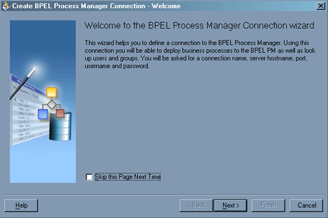
Click Next.
The Create BPEL Process Manager Connection dialog box is displayed.
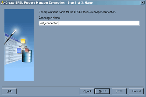
Specify a unique name for your BPEL Server connection and click Next.
The Create BPEL Process Manager Connection dialog box is displayed.
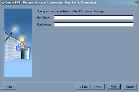
Specify a valid host name and port number for the BPEL PM Server you wish to connect to.
Click Finish.
Your newly created server connection is displayed in the Connections tab under the BPEL Process Manager Server node.
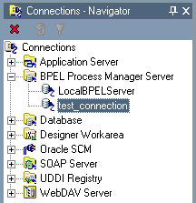
Create a New BPEL Project for Outbound Interaction (Synchronous Process)
To create a new BPEL project for a synchronous process:
At the bottom of the upper left pane, click the Applications tab and select a workspace for your project.

Right-click the workspace and select New Project.
The New Gallery window is displayed.
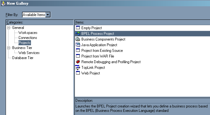
From the Items list, select BPEL Process Project and click OK.
The BPEL Process Project dialog box is displayed.

Perform the following steps:
Specify a name for the BPEL process.
The Namespace field is updated automatically.
From the Template drop-down list, select Synchronous BPEL Process.
Click OK.
Create an Outbound PartnerLink Activity
When designing a BPEL process, a PartnerLink activity must be created to invoke the Siebel service. A PartnerLink describes a set of operations within a Web service. The WSDL document is the external contract to which the Web service conforms. Given a WSDL, any BPEL process can initiate a Web service through a PartnerLink.
To create an outbound PartnerLink using the WSDL file you generated in Application Explorer:
From the Process Activities pane on the right, drag and drop a PartnerLink to the visual editor.
The Create Partner Link dialog box is displayed.
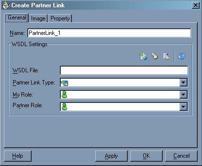
Click the WSIL browser icon (second icon from the left the WSDL File field).
The WSDL Chooser dialog box is displayed.

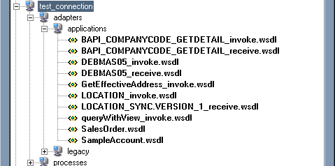
Expand your new connection, then expand adapters, and then applications.
The WSDL tree displayed in the WSDL Chooser dialog box lists any WSDL files you have created using Application Explorer. The WSDL tree is generated by a WSDL servlet, which is automatically deployed as part of the BPEL Server installation.
|
Note: If you have organized your WSDL files in subfolders, the WSIL browser will display the full tree structure of your WSDL hierarchy. By default, the names of all WSDL files generated for outbound adapter services end with_invoke.
|
Select queryWithView_invoke.wsdl and click OK.
The WSDL File field in the Create Partner Link dialog box displays the name and location of the selected WSDL file. The Partner Link Type field specifies the PartnerLink defined in the WSDL file.
Perform the following steps:
Leave the My Role field unspecified. The role of the PartnerLink is null, as it will be synchronously invoked from the BPEL process.
From the Partner Role drop-down list, select the default value queryWithViewRole. This is the role of the BPEL process.
Click OK.
The new PartnerLink appears in the visual editor.
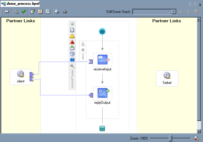
Select Save from the File menu.
Create an Outbound Invoke Activity
This activity enables you to specify an operation you want to invoke for the service identified by its PartnerLink. The Invoke activity opens a port in the process that is used to send and receive data. It uses this port to submit required data and receive a response. For synchronous callbacks, only one port is needed for both the send and the receive functions.
To create an outbound Invoke activity:
From the Process Activities pane on the right, drag an Invoke activity to the visual editor and place it between the Receive activity (receiveInput) and the Reply activity (replyOutput).
Extend a connection between the Invoke activity and your newly-created PartnerLink.
The Edit Invoke dialog box is displayed. Note that the Partner Link and Operation fields are automatically populated with your WSDL files.
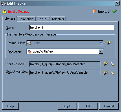
In the Name field, provide a meaningful name for the Invoke activity.
Click the first icon to the right of the Input Variable field, then click OK in the Create Variable window that is displayed.
A global variable is automatically created in the Input Variable field.
Click the first icon to the right of the Output Variable field, then click OK in the Create Variable window that is displayed.
A global variable is automatically created in the Output Variable field.
Click Apply.
The Edit Invoke window should no longer display any warnings or errors.
Click OK.
Select Save from the File menu.
Create an Assign Activity
An Assign activity provides a method for simple data manipulation, such as copying the contents of one variable to another. This Assign activity maps the input variable of the Siebel process to the Siebel PartnerLink input.
To create an Assign activity:
From the Process Activities pane on the right, drag an Assign activity to the visual editor and place it between the Receive activity (receiveInput) and the new Invoke activity (Invoke_1).
Double-click the Assign activity icon.
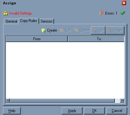
The Assign dialog box is displayed.
|
Note: Ignore any invalid settings and error warnings. |
In the Copy Rules tab, click Create.
The Create Copy Rule dialog box is displayed.
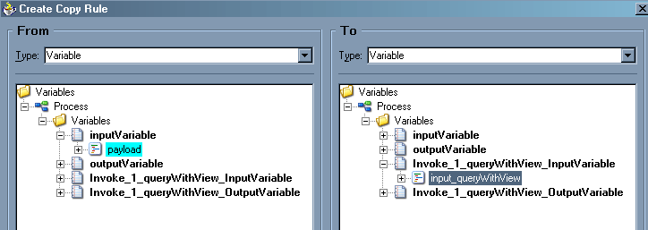
In the From pane, expand Variables, then inputVariable, and then highlight payload.
In the To pane, expand Variables, then Invoke_1_queryWithView_InputVariable, and then highlight input_queryWithView.
Your Create Copy Rule dialog box should look as follows:
To close the Create Copy Rule dialog box and the Assign dialog box, click OK.
Create a Second Assign Activity
This Assign activity maps the output variable of the Siebel process to the Siebel PartnerLink output.
To create a second Assign activity:
From the Process Activities pane on the right, drag another Assign activity to the visual editor and place it between the Invoke activity (Invoke_1) and the Reply activity (replyOutput).
Double-click the Assign activity icon.
The Assign settings dialog box is displayed.

In the Copy Rules tab, click Create.
The Create Copy Rule dialog box is displayed. Perform the following steps:
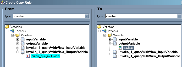
In the From pane, expand Variables, then Invoke_1_queryWithView_OutputVariable, and then highlight output_queryWithView.
In the To pane, expand Variables, then outputVariable, and then highlight payload.
Your Create Copy Rule dialog box should look as follows:
To close the Create Copy Rule dialog box and the Assign dialog box, click OK.
Select Save from the File menu.
The following image shows the diagram view of your completed BPEL process.
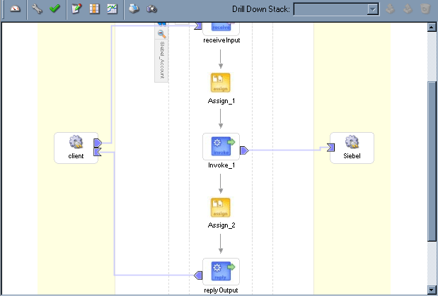
See Invoking Adapter Request-Response Service from BPEL Process Manager for information on how to deploy and manage your outbound process.
|
See Also:
|
An inbound BPEL process consists of a PartnerLink and a Receive process activity. You must first create a channel and a new BPEL Process Manager Server connection. See Chapter 5, "BPEL Process Manager Integration Examples" for complete instructions on how to perform these procedures.
|
Note: You must create a separate channel for every inbound J2CA service and select that channel when you generate WSDL for inbound interaction using Application Explorer. Do not start the channel in Application Explorer, as BPEL Process Manager manages endpoint activation independently. See Siebel Event Integration for more information. |
Create a New BPEL Project for Inbound Interaction (Empty Process)
Before you create a BPEL project, verify that your BPEL Server is running. After you have created a new server connection, you are ready to design an empty process template for your BPEL project. See Create a New Connection to BPEL PM Server for complete instructions on how to create a server connection.
To create a new BPEL project for inbound interaction:
Click the Applications tab and select a workspace for your project.

Right-click the workspace and select New Project.
The New Gallery window is displayed.

From the Items list, select BPEL Process Project and click OK.
The BPEL Process Project dialog box is displayed.
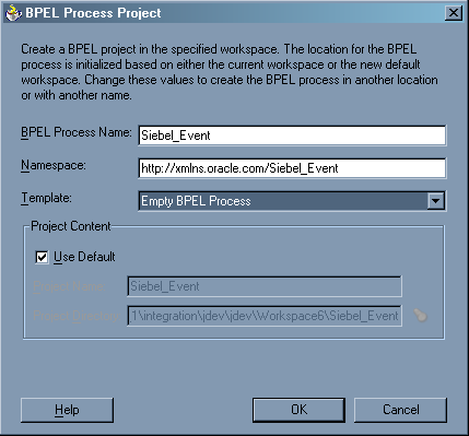
Perform the following steps:
Specify a name for the process.
The Namespace field is updated automatically.
From the Template drop-down list, select Empty BPEL Process.
Click OK.
Create an Inbound PartnerLink Activity
When designing a BPEL process, a PartnerLink activity must be created to invoke the Siebel service. A PartnerLink describes a set of operations within a Web service. The WSDL document is the external contract to which the Web service conforms. Given a WSDL, any BPEL process can initiate a Web service through a PartnerLink.
To create an inbound PartnerLink using the WSDL file you generated in Application Explorer:
From the Process Activities pane on the right, drag and drop a PartnerLink to the visual editor.
The Create Partner Link dialog box is displayed.

Click the WSIL browser icon (second icon from the left before the WSDL File field).
The WSDL Chooser dialog box is displayed.

Expand your new server connection, then expand adapters, and then applications.
The WSDL tree displays the WSDL files you created using Application Explorer. The WSDL tree is generated by a WSDL servlet, which is automatically deployed as part of the BPEL Server installation.

|
Note: If you have organized your WSDL files in subfolders, the WSIL browser will display the full tree structure of your WSDL hierarchy. By default, the names of all WSDL files generated for inbound adapter services end with_receive.
|
Select SampleAccount.wsdl and click OK.
The Create Partner Link dialog box is displayed.
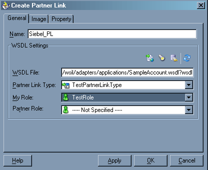
The WSDL File field displays the name and location of the selected WSDL file. The Partner Link Type field specifies the PartnerLink defined in the WSDL file.
Perform the following steps:
From the My Role drop-down list, select the default value TestRole.
Leave the Partner Role field unspecified.
Click Apply, and then OK.
The new Siebel PartnerLink appears in the visual editor.
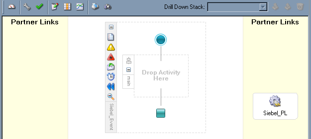
Select Save from the File menu.
Create an Inbound Receive Activity
To create an inbound Receive Activity:
From the Process Activities pane on the right, drag a Receive activity to the visual editor and place it in the designated placeholder labeled Drop Activity Here.
Connect the Receive activity to the Siebel_PL PartnerLink.
The Edit Receive dialog box is displayed.
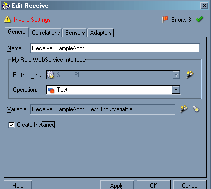
Perform the following steps:
Click Apply.
The Receive dialog box should no longer display any warnings or errors.
Click OK.
A connection is created between the PartnerLink and the Receive activity. You have completed the design of your inbound BPEL process.
See Listening to Adapter Events Inside BPEL Process Manager for information on how to deploy and manage your inbound process.
|
See Also:
|
The OracleAS Adapter for Siebel request-response service is used to create, delete, update, and query back-end data as well as to call back-end workflows and transactions. The following section describes how to invoke the adapter synchronous request-response service, also referred to as Outbound Interaction, as well as how to manage the process in Oracle BPEL Console.
Deploy the Outbound BPEL Process
The procedures for deploying an inbound and an outbound BPEL process using the JDeveloper interface are identical.
To deploy your BPEL process in JDeveloper:
Right-click your process flow in the Applications - Navigator pane.
Select Deploy > Your BPEL PM Server connection > Deploy to default domain.
The Password Prompt dialog box is displayed.
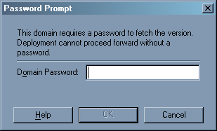
In the Domain Password field, enter your BPEL Process Manager password.
The deployment process starts automatically after you enter the correct password.
Observe the Messages log on the bottom of the window.
The Messages log displays the deployment status. In this example, it shows a successful deployment message for the process.

If deployment was not successful, click the Compiler tab to view all error and warning messages generated during the deployment process.
Manage the Deployed Outbound Process in Oracle BPEL Console
JDeveloper deploys the developed process directly to the Oracle BPEL Console, which allows you to run, monitor, and administer BPEL processes.
To invoke adapter request-response service:
Start the Oracle BPEL Console by entering the following URL in a browser:
http://host:port/BPELConsole
Select a domain and provide a valid password.
The Oracle BPEL Console main page is displayed. All deployed BPEL processes are listed in the Dashboard tab.
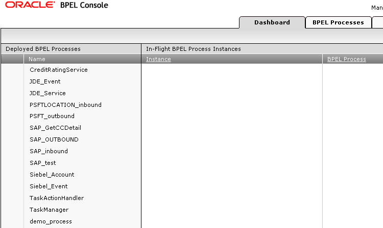
This tab provides a more detailed view of each deployed process.

Click the Siebel_Account process link.
The Manage window provides options for managing this BPEL process. Do not change any of the following default settings.
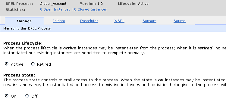
Click the Initiate tab.
The Initiate tab enables you to test your BPEL process.
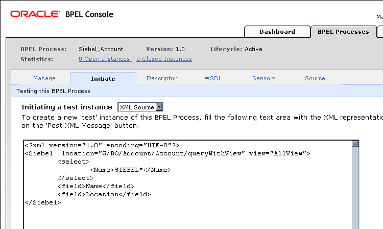
Perform the following steps:
From the Initiating a test instance drop-down menu, select XML Source.
Enter the following code in the text area provided for XML input:
<?xml version="1.0" encoding="UTF-8"?>
<Siebel  location="S/BO/Account/Account/queryWithView" view="AllView">
  <select>
    <Name>SIEBEL*</Name>
  </select>
  <field>Name</field>
  <field>Location</field>
</Siebel>
Click Post XML Message.
The response received from the Siebel system is displayed in the Initiate window.
|
See Also: Oracle Application Server Adapter Concepts |
The OracleAS Adapter for Siebel event notification service, also referred to as Inbound Interaction, is used to listen to events that occur in an EIS. The following section describes how to deploy your inbound BPEL process and listen to adapter events at runtime using Oracle BPEL Console.
Deploy the Inbound BPEL Process
The procedures for deploying an inbound and an outbound BPEL process using the JDeveloper interface are identical.
To deploy your BPEL process in JDeveloper:
Right-click your process flow in the Applications pane.
Select Deploy > Your BPEL PM Server connection > Deploy to default domain.
The Password Prompt dialog box is displayed.

In the Domain Password field, enter your BPEL Process Manager password.
The deployment process starts automatically after you enter the correct password.
Observe the Messages log on the bottom of the window.
The Messages log displays the deployment status. In this example, it shows a successful deployment message for the process.

If deployment was not successful, click the Compiler tab to view all error and warning messages generated during the deployment process.
Listen to Adapter Events in Oracle BPEL Console
JDeveloper deploys the developed process directly to Oracle BPEL Console, which allows you to run, monitor, and administer BPEL processes, as well as to listen to adapter events at runtime using Oracle BPEL Console.
To listen to adapter events:
Start the Oracle BPEL Console by entering the following URL in a browser:
http://host:port/BPELConsole
Select a domain and provide a valid password.
The Oracle BPEL Console Dashboard tab is displayed.
Click the Instances tab.
Upon receiving a runtime event, an instance of the event is displayed under the Instances tab.

To see the event message, click the instance, and then click Audit.
The message received from the Siebel system is displayed in the Audit tab. Click More... to view the entire message, or View Raw XML to view the XML source.
See Chapter 5, "BPEL Process Manager Integration Examples" for more information.
|
See Also: Oracle Application Server Adapter Concepts |