|
Oracle® Application Server Adapter for Oracle Applications User's Guide
10g Release 2 (10.1.2) B16498-02 |
|
 Previous |
 Next |
|
Oracle® Application Server Adapter for Oracle Applications User's Guide
10g Release 2 (10.1.2) B16498-02 |
|
 Previous |
 Next |
Oracle XML Gateway provides a common, standards-based approach for XML integration between Oracle Applications and third party applications, both inside and outside your enterprise. XML is key to an integration solution, as it standardizes the way in which data is searched, exchanged, and presented thereby enabling interoperability throughout the supply chain.
This chapter includes the following sections:
Design-Time Steps for XML Gateway Inbound into Oracle Applications
Run-Time Steps for XML Gateway Inbound into Oracle Applications
Design-Time Steps for XML Gateway Outbound from Oracle Applications
Run-Time Steps for XML Gateway Outbound from Oracle Applications
Oracle XML Gateway is a set of services that allows easy integration with Oracle Applications to support XML messaging. Oracle Applications utilize the Oracle Workflow Business Event System to support event-based XML message creation and consumption.
OracleAS Adapter for Applications can be configured to use XML Gateway to interact with third party applications. The tight integration provided by open interface tables is not suitable for those scenarios where trading partners change frequently. XML Gateway is an ideal solution when you need to interact with third party applications that use open standards. Morevoer, it is also suitable for scenarios where trading partners change frequently.
As a provider of broad based business application solutions to support all industries, Oracle XML Gateway supports all Document Type Definition (DTD) based XML standards. The majority of the Oracle prebuilt messages delivered with Oracle Applications are premapped using the Open Application Group (OAG) standard. Any Oracle prebuilt message map may be remapped to your standard of choice using the XML Gateway Message Designer.
XML Gateway provides an application integration infrastructure that is flexible enough to accomodate the integration requirements of any application that needs to integrate with Oracle Applications. XML Gateway enables you to create an efficient and responsive supply chain that links all customers, factories, warehouses, distributors, carriers, and other trading partners. All these entities can seamlessly operate as a single enterprise.
Oracle XML Gateway supports both Business-to-Business (B2B) and Application-to-Application (A2A) initiatives. B2B initiatives include communicating business documents and participating in industry exchanges. An example of an A2A initiative is data integration with legacy and disparate systems.
XML Gateway enables bidirectional integration with Oracle Applications by allowing you to insert and retrieve data from Oracle Applications. The Oracle Applications adapter for XML Gateway supports two operations, namely, enqueue and dequeue. The enqueue operation is used to put messages in the queue. This is used to insert inbound data into Oracle Applications. The dequeue operation polls for messages from the queue. This is used to retrieve outbound data from Oracle Applications. Only one operation can be defined for each adapter service.
Figure 6-1 shows the integration architecture for XML Gateway.
Figure 6-1 XML Gateway Integration Architecture
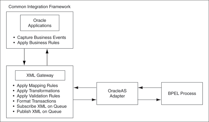
The XML Gateway uses queues specifically at two points in the proces as well as employing a general error queue. The first point is at the transport agent level between the transport agent module and the XML Gateway. The second point is at the transaction level between base Oracle Applications products and the XML Gateway.
Inbound message queues are used for XML messages inbound into Oracle Applications. Inbound message queues are positioned between the Transport Agent and the Oracle Workflow Business Event System.
The messages must be formatted according to the XML Gateway envelope message format. The envelope message format is discussed under XML Gateway Envelope. Oracle Workflow Business Event System copies the inbound messages to the proper inbound Transaction Queue.
Outbound message queues are used for XML messages outbound from Oracle Applications. The outbound Message Queue is positioned between the XML Gateway and the Transport Agent.
The XML Gateway creates XML messages, then enqueues them on this queue. The Transport Agent dequeues the message and delivers it to the Trading Partner.
In addition to the business document such as a purchase order or invoice in the XML Payload, a set of message attributes are also transmitted. Collectively, these attributes are called the XML Gateway envelope. This subsection discusses some of these attributes.
Payload message format. This defaults to XML. Oracle XML Gateway currently supports only XML.
Message format standard as displayed in the Define Transactions form and entered in the Define XML Standards form. This defaults to OAG. The message standard entered for an inbound XML document must be the same as the message standard in the trading partner setup.
External Transaction Type for the business document from the Trading Partner table. The transaction type for an inbound XML document must be the same as the transaction type defined in the Trading Partner form.
External Transaction Subtype for the business document from the Trading Partner table. The transaction subtype for an inbound XML document must be the same as the transaction subtype defined in the Trading Partner form.
The document identifier used to identify the transaction, such as a purchase order or invoice number. This field is not used by the XML Gateway, but it may be passed on inbound messages.
This is the Source Trading Partner Location Code.
Transmission Protocol as defined in the Trading Partner table.
Transmission address as defined in the Trading Partner table.
USERNAME as defined in the Trading Partner table.
The password associated with the USERNAME defined in the Trading Partner table.
The party site identifier for an inbound XML document must be the same as the Source Trading Partner location defined in the Trading Partner form.
For outbound messages, this field has the value from the Destination Trading Partner Location Code in the Trading Partner table. For inbound messages, the presence of this value generates another XML message that is sent to the trading partner identified in the Destination Trading Partner Location Code in the Trading Partner table. This value must be recognized by the hub to forward the XML message to the final recipient of the XML Message.
|
See Also: Destination Trading Partner Location Code section on page 199 of the Oracle XML Gateway User's Guide. This guide is a part of the Oracle Applications documentation library. Oracle Applications documentation can be accessed from the following link:
|
The XML message.
Parameters defined by the Application
The following parameters may be defined by the base application:
ATTRIBUTE1
ATTRIBUTE2
ATTRIBUTE4
ATTRIBUTE5
The following parameters are not used:
PARTYID
PARTYTYPE
|
See Also: Oracle XML Gateway User's Guide for details on the XML Gateway Execution Engine, Trading Partner validation, and so on. This guide is a part of the Oracle Applications documentation library. Oracle Applications documentation can be accessed from the following link:
|
OracleAS adapter for Oracle Applications is deployed using the BPEL Process Manager (PM) in Oracle JDeveloper. The BPEL PM creates the WSDL interfaces for the XML Gateway message map.
This section describes configuring the OracleAS Adapter for Oracle Applications to use XML Gateway. It includes the following topics:
You need to populate certain variables in the BPEL PM in order to provide context information for Oracle Applications. The MESSAGE_TYPE, MESSAGE_STANDARD, TRANSACTION_TYPE, TRANSACTION_SUBTYPE, and PARTY_SITE_ID are the mandatory header variables that you need to populate for the XML transaction to complete successfully. Refer to Chapter6, "Configuring the Assign Activity" for more information.
You also need to configure and schedule two listeners on the Oracle Applications side. These are the ECX Inbound Agent Listener and the ECX Transaction Agent Listener. Use the following steps to configure these listeners in Oracle Applications:
Log in to Oracle Applications with the responsibility of Workflow Administrator.
The Navigator page is displayed. Click the Workflow Administrator Web Applications link.
Click the Workflow Manager link under Oracle Applications Manager.
Click the status icon next to Agent Listeners.
Configure and schedule the ECX Inbound Agent Listener and the ECX Transaction Agent Listener. Select the listener, and select Start from the Actions box. Click Go.
This section describes the tasks required to configure OracleAS Adapter for Oracle Applications using the Adapter Configuration Wizard in Oracle JDeveloper. This section covers the following:
Use the following steps to create a new BPEL project:
Open JDeveloper BPEL Designer.
From the File menu, select New. The New Gallery dialog box is displayed.
Select All Items from the Filter By box. This displays a list of available categories.
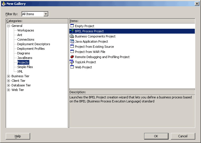
Expand the General node, and then select Projects.
Select BPEL Process Project from the Items group, as shown in Figure 6-2.
Figure 6-2 Creating a New BPEL Process Project
Click OK. The BPEL Process Project dialog box is displayed.
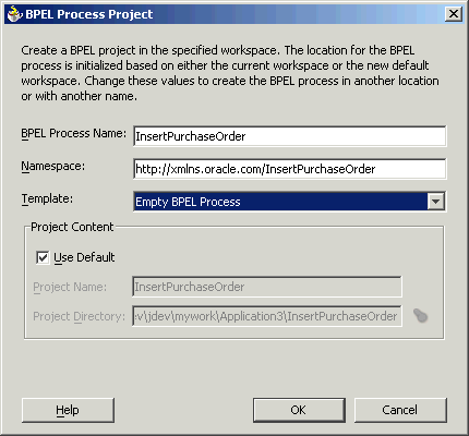
In the BPEL Process Name field, enter a descriptive name. For example, InsertPurchaseOrder.
From the Template box, select Empty BPEL Process. Keep the default selection for Use Default under Project Content, as shown in Figure 6-3.
Figure 6-3 Specifying a Name for the New BPEL Process Project
Click OK. A new BPEL process, with the required source files including bpel.xml, InsertPurchaseOrder.bpel, and InsertPurchaseOrder.wsdl, is created as shown in Figure 6-4.
The next task is to add a partner link to the BPEL process. A partner link defines the link name, type, and the role of the BPEL process that interacts with the partner service.
Use the following steps to add a partner link:
Drag and drop PartnerLink, from the Component Palette, into the border area of the process diagram. The Create Partner Link dialog box is displayed.
Click the Define Adapter Service icon in WSDL Settings. The Adapter Configuration Wizard is displayed.
Click Next. The Adapter Type dialog box is displayed.
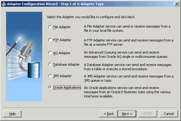
Select Oracle Applications, as shown in Figure 6-5. Click Next.
Figure 6-5 Selecting OracleAS Adapter for Oracle Applications
The Service Name dialog box is displayed, as shown in Figure 6-6. Enter the following information:
In the Service Name field, enter a service name.
In the Description field, enter a description for the service. This is an optional field. Click Next.
The Service Connection dialog box is displayed. Enter the Java Naming and Directory Interface (JNDI) name in the Database Server JNDI Name field. The JNDI name acts as a placeholder for the connection used when your service is deployed to the BPEL server. This enables you to use different databases for development and later production.
Figure 6-7 shows how to create a new database connection.
Figure 6-7 Creating a New Database Connection
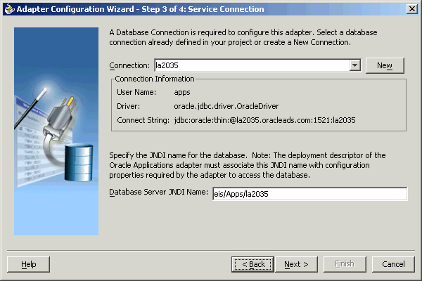
Click New to define a database connection. The Create Database Connection Wizard is displayed.
|
Note: You need to connect to the database where Oracle Applications is running. |
Enter the following information in the Type dialog box:
In the Connection Name field, specify a unique name for the database connection.
From the Connection Type box, select the type of connection for your database connection.
Figure 6-8 shows the Type dialog box.
Figure 6-8 Specifying the Connection Name and Type of Connection
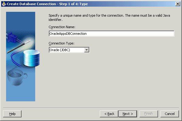
Click Next. The Authentication dialog box is displayed.
Enter information in the following fields:
In the UserName field, specify a unique name for the database connection.
In the Password field, specify a password for the database connection.
Click Next. The Connection dialog box is displayed.
Enter information in the following fields:
From the Driver list, select Thin.
In the Host Name field, specify the host name for the database connection.
In the JDBC Port field, specify the port number for the database connection.
In the SID field, specify a unique SID value for the database connection.
Figure 6-9 shows the Connection dialog box.
Figure 6-9 Specifying the New Database Connection Information
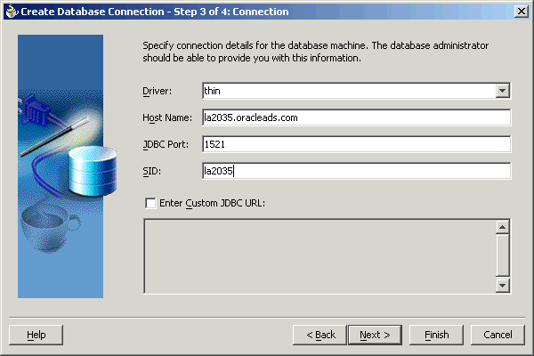
Click Next. The Test dialog is displayed.
Click Test Connection to determine whether the specified information establishes a connection with the database.
Click Next. The Service Connection dialog box is displayed, providing a summary of the database connection.
Click Finish to complete the process of creating a new database connection.
Once you have completed creating a new connection for the service, you can add an XML Gateway map by browsing through the maps available in Oracle Applications.
Click Next in the Service Connection dialog box. The Operation dialog box is displayed.
|
Note: If you are connecting to a pre-11.5.10 Oracle Applications instance, then you would be required to select the interface to Oracle Applications data. Select XML Gateway to proceed. Select Enqueue or Dequeue depending on whether data is inbound into Oracle Applications or outbound from Oracle Applications. Next, choose the DTD file that is converted into an XSD schema file. |
Click Get Object to open the Oracle Applications Module Browser. Figure 6-10 shows the Oracle Applications Module Browser.
Figure 6-10 Specifying the XML Gateway Message Map
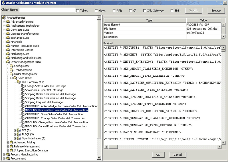
Oracle Applications Module Browser includes the various product families that are available in Oracle Applications. For example, the Marketing Suite or the Order Management Suite are product families in Oracle Applications. The product families contain the individual products. For example, the Order Management Suite contains the Order Management product. The product contains the business entities associated with the product. For example, the Order Management product contains the Sales Order business entity.
Business entities contain the various application modules that are exposed for integration. These modules are grouped accoding to the interface they provide. XML Gateway message maps can be found under the XML Gateway category.
Select an inbound or outbound XML Gateway message map. Click OK. You can select only one XML Gateway message map for each adapter service. The XML schema is generated. Figure 6-11 shows that the XML Gateway map that has been added.
|
Note:
|
Click Next.
Click Finish. When you click Finish, the wizard generates the WSDL file corresponding to the XML schema. This WSDL file is now available for the partner link. Figure 6-12 shows the Create partner Link dialog box.
Figure 6-12 Completing the Partner Link Configuration

Click OK. The partner link is created with the required WSDL settings.
After adding and configuring the partner link, the next task is to configure the BPEL process itself. You can start by configuring the Invoke process activity to enqueue the XML Gateway inbound messages.
The following steps discuss configuring the Invoke activity:
Drag and drop Invoke into the process map window. Figure 6-13 shows the Invoke activity after it has been added to the process map.
Double-click Invoke in the process map to open the Invoke dialog box. The General tab is selected by default. Figure 6-14 shows the Invoke dialog box.
Figure 6-14 Configuring the Invoke Activity
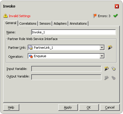
In the Partner Link box, select the partner link to invoke. This is the partner link that you configured in the previous section. The Operation is automatically selected, depending on the message map that you chose when configuring the partner link. If you selected an inbound message map, then the Enqueue operation is selected.
Click the Create icon next to the Input Variable field. Enter a descriptive name for the variable in the Create Variable dialog box that appears. You can also accept the default name. Click OK. Figure 6-15 shows the Create Variable dialog box.
Click the Adapters tab in the Invoke dialog box. You need to specify the Input Header Variable here. Click the Browse icon next to the Input Header Variable field.
In the Variable Chooser dialog box that appears, select the Variables node and click Create. Figure 6-16 shows the Variable Chooser dialog box.
Figure 6-16 Specifying the Input Header Variable

The Create Variable dialog box is displayed. Figure 6-17 shows the Create Variable dialog box. Type a descriptive name for the variable in the Name field. Select the Message Type option and click the Browse icon next to it.
Figure 6-17 Creating the Input Header Variable
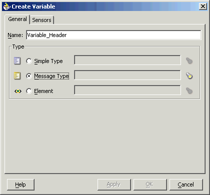
In the Type Chooser dialog box that appears, select the appropriate message type and click OK. Figure 6-18 shows the Type Chooser dialog box.
In the Create Variable dialog box, click OK. In the Variable Chooser dialog box, click OK.
In the Invoke dialog box, click Apply. Click OK.
|
Note: If you have configured a partner link for outbound messages from Oracle Applications, then you need to configure a Receive activity in place of the Invoke activity. The Receive activity is used to dequeue the XML Gateway outbound messages. |
If you are configuring an inbound message, then you would need to add another partner link for the file adapter. This allows the inbound message to pick up an XML file received from the third party application. The data is inserted into Oracle Applications through the partner link that was configured earlier. Use the following steps to add a partner link for the file adapter:
Drag and drop PartnerLink into the border area of the process diagram. The Create Partner Link dialog box is displayed.
Click the Define Adapter Service icon in the WSDL Settings section. The Adapter Configuration Wizard is displayed.
Click Next. The Adapter Type dialog box is displayed.
Select File Adapter. Click Next.
Enter a name for the file adapter service in the Service Name field. You can also enter an optional description. Figure 6-19 shows the Service Name dialog box. Click Next.
The Operation dialog box is displayed. Select the Operation Type. The Operation Type specifies whether you are polling for files or creating outgoing files. Select Read File if you need to read files for inbound operations. Enter a name for the Operation in the Operation Name field. You can also use the default name. Figure 6-20 shows the Operation dialog box. Click Next.
Figure 6-20 Specifying the Operation Name and Type

|
Note: If you are configuring the BPEL Process for outbound XML messages from Oracle Applications, then you need to choose Write File in place of Read File. |
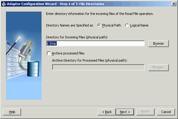
The File Directories dialog box is displayed. Enter the physical path for the XML files. You can also choose the location by using Browse. Figure 6-21 shows the File Directories dialog box. Click Next.
Figure 6-21 Specifying the Physical Path for the XML Files
The File Filtering dialog box is displayed. This enables you to specify the pattern using which you want to match the XML files that need to be picked. Figure 6-22 shows the File Filtering dialog box. Specify a pattern and click Next.
Figure 6-22 Specifying File Filtering Parameters for the Read Operation

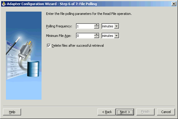
The File Polling dialog box is displayed. You need to specify the frequency at which the directory needs to be polled for the XML files. Specify a Polling Frequency. Click Next. Figure 6-23 shows the File Polling dialog box.
Figure 6-23 Specifying the Polling Frequency
The Messages dialog box is displayed, as shown in Figure 6-24. You need to specify the schema file location and select the schema element that defines the messages in the incoming files. You can use Browse to select the schema file location. Enter the required information, and then lick Next.
Figure 6-24 Specifying the Schema File Location and Schema Element
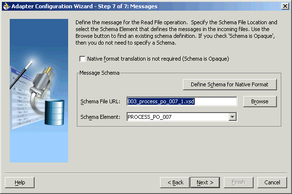
Click Finish to finish creating the File Adapter service. Click OK in the Create Partner Link dialog box to create the partner link for the File Adapter service.
|
Note: The File Adapter is just one of the ways to read or write XML messages. The XML messages can also be exchanged using an FTP Adapter, SMTP Adapter, or through another BPEL process. |
The next task is to configure a Receive activity to receive XML data from the partner link that you configured for the file adapter service. Use the following steps to configure the Receive activity:
Drag and drop Receive into the process map window. The Receive activity should be placed in between Start and Invoke. Figure 6-25 shows the process map window after the Receive activity has been added.
Double-click Receive in the process map to open the Receive dialog box. The General tab is selected by default. Figure 6-26 shows the Receive dialog box.
Figure 6-26 Configuring the Receive Activity

In the Partner Link box, choose the partner link corresponding to the file adapter service. The Operation is selected by default depending on the Partner Link that you select.
Click the Create icon next to the Variable field.
The Create Variable dialog box appears. Enter a Name for the variable. You can also accept the default name. Click OK. Figure 6-27 shows the Create Variable dialog box.
Figure 6-27 Creating the Receive Variable
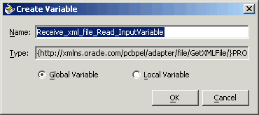
Click Apply in the Receive dialog box, and then click OK. This associates the Receive activity with the partner link configured for the file adapter service.
|
Note: If you are configuring the process for outbound XML messages from Oracle Applications, then you need to link the file adapter partner link to the Invoke activity. The Invoke process activity invokes the file adapter interface to write the XML message to an XML file. |
The next task is to add an Assign activity to the process map. This is used to populate parameters that provide context information to Oracle Applications. The following steps discuss this task:
Drag and drop the Assign activity to the process map. The Assign activity needs to be dropped in between the Receive and Invoke activities. Figure 6-28 shows the process map as it appears after adding the Assign activity.
You now need to configure the Assign activity. Double-click the Assign activity in the process map.
The Assign dialog box is displayed. The Copy Rules tab is displayed by default. Click Create.
The Create Copy Rule dialog box is displayed. In the To group, expand the Variables node by clicking the plus sign next to it. Expand the Variable_Header, Header, ns1:Header, and the ns1:PayloadHeader child nodes. Figure 6-29 shows the Create Copy Rule dialog box.
Figure 6-29 Specifying Context Information for Oracle Applications

Select the MESSAGE_TYPE variable. In the From group, select Expression as the Type. Enter a MESSAGE_TYPE in the Expression field. The MESSAGE_TYPE would be 'XML' for XML Gateway. Click OK.
Repeat steps 3 and 4. Select the MESSAGE_STANDARD variable. MESSAGE_STANDARD is the XML message standard that you are using. Enter an Expression for the MESSAGE_STANDARD, say 'OAG'. Click OK.
Repeat steps 3 and 4. Select the TRANSACTION_TYPE variable. This variable defines the type of transaction that you are performing, say a purchase order operation. Enter an Expression for the TRANSACTION_TYPE, say 'PO'. Click OK.
Repeat steps 3 and 4. Select the TRANSACTION_SUBTYPE variable. This variable defines the subtype for the transaction that you are performing. Enter an Expression for the TRANSACTION_SUBTYPE, say 'Process'. This means that you are processing a Purchase Order TRANSACTION_TYPE. Click OK.
Repeat steps 3 and 4. Select the PARTY_SITE_ID variable. The PARTY_SITE_ID identifies the trading partner. Enter an Expression for the PARTY_SITE_ID. Click OK.
|
Note: TheMESSAGE_TYPE, MESSAGE_STANDARD, TRANSACTION_TYPE, TRANSACTION_SUBTYPE, and PARTY_SITE_ID are the mandatory header variables that you need to populate for the XML transaction to complete successfully.
|
After designing the BPEL process, the next step is to deploy, run and monitor it. This section disscusses the following:
You need to deploy the BPEL process before you can run it. The BPEL process is first compiled and then deployed to the BPEL server. The following steps discuss deploying the BPEL process to a BPEL server:
Select the BPEL project in the Applications window.
Right-click the project name. Select Deploy from the menu that appears.
Select Local BPEL Server followed by Deploy to Default Domain, if you are deploying the process on the local BPEL server. Figure 6-30 illustrates deploying a BPEL process to a local BPEL server.
|
Note: You can select Invoke Deployment Tool if you want to deploy to a different BPEL server. |
The Password Prompt dialog box appears. Enter the password for the default domain in the Domain Password field. Click OK. Figure 6-31 shows the Password Prompt dialog box.
Figure 6-31 Specifying the Domain Password
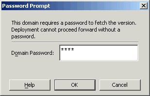
The BPEL process is compiled and deployed. You can check the progress in the Messages window. Figure 6-32 shows the Messages window.
Once the BPEL process is deployed, it can be seen in the BPEL console. You can manage and monitor the process from the BPEL console. You can also test the process and the integration interface by manually initiating the process. The following steps discuss manually initiating and monitoring the BPEL process:
To open the BPEL console, click Start, and then choose Programs. In the Programs menu, select Oracle - ORACLE_HOME, Oracle BPEL Process Manager 10.1.2, and then select BPEL Console.
The BPEL console login screen is displayed. Select Default in the Domain box. Enter the password for the default domain in the Password field. Click Login. Figure 6-33 shows the BPEL console login screen.
Oracle BPEL console is displayed. The list of deployed processes is shown under Deployed BPEL Processes. Figure 6-34 shows the BPEL console screen.
Click the BPEL process that you want to initiate. The Initiate page is displayed. Enter the input values required by the process. You can also specify an XML file for the file adapter to pick.
Click Post XML Message to initiate the process.
The BPEL process is now initiated. You can check the process flow by clicking the Visual Flow icon. Figure 6-35 shows the BPEL Console Initiate page.
The audit trail provides information on the steps that have been executed. The audit trail also records the Reference ID that is returned for the transaction. You can check the audit trail by clicking the Audit Instance icon.
If the BPEL process runs into an error, then a corresponding error code is returned. Table 6-1 lists the common error codes, their descriptions, and the fix that you can use for them.
Table 6-1 Error Codes for the BPEL Process
| Code No. | Code Name | Description | Fix |
|---|---|---|---|
|
12400
|
|
Message Standard not set in the header
|
Set the Message Standard value in the header
|
|
12401 |
|
Transaction Type not set in the header |
Set the Transaction Type value in the header |
|
12402 |
|
Transaction Subtype not set in the header |
Set the Transaction Subtype value in the header |
|
12403 |
|
Party Site Id not set in the header |
Set the Party Site Id value in the header |
|
12404 |
|
Message Type not set in the header |
Set the Message Type value in the header |
|
12406 |
|
Error in setting Apps Context |
Check the username and responsibility values |
|
12407 |
|
Invalid FND username/password |
Check the username and password values |
|
12408 |
|
Unknown error in Apps Interaction |
Check if all the header values are valid |
|
12409 |
|
XML Gateway header is null |
Pass the required parameters in header |
You can verify all successful entries in Oracle Applications. You need to look at the relevant module in Oracle Applications to check for the new records. For example, you can look for a Sales Order entry in the Order Management module.
You can check for unsuccessful entries in corrections. You can use the Reference ID of a transaction to look for a particular record. This is the same Reference ID that you noted in the BPEL audit trail. You can reprocess a record after making the necessary configuration changes. However, you cannot alter the data in the record.
The Transaction Monitor is a tool for monitoring the status of inbound and outbound transactions originating from and going into Oracle Applications that have been processed by the XML Gateway and delivered or received by the Oracle Transport Agent. The Transaction Monitor shows a complete history and audit trail of these documents.
You can navigate to the Transaction Monitor page using the Workflow Administrator Web responsibility. The Transaction Monitor provides the following:
Flexible search criteria to support access to a specific document or group of documents
Search results at the document header level with drill down by document ID
Resend capability for outbound messages
Viewing capability of the XML message content
|
See Also: Oracle XML Gateway User's Guide for details on using the Transaction Monitor. This guide is a part of the Oracle Applications documentation library. Oracle Applications documentation can be accessed from the following link:
|
This section discusses the design-time steps, for an XML Gateway outbound message, that are different from the design-time steps for an inbound message. This section includes the following topics:
For invoking an outbound partner link, you need to set up the correlation identifier in Oracle Applications. The correlation identifier enables you to label messages meant for a specific agent, in case there are multiple agents listening on the outbound queue. The agent listening for a particular correlation picks up the messages that match the correlation identifier for the agent. You can use the following steps to set up the correlation identifier:
Log in to Oracle Applications with the XML Gateway responsiblity. The Navigator page is displayed.
Click the XML Gateway link.
Click the Define Lookup Values link under XML Gateway.
Enter COMM_METHOD for the Type field.
Enter BPEL for the Code field. Fill in the other mandatory fields. Oracle XML Gateway puts the correlation of BPEL when enqueueing the message on the ECX_OUTBOUND queue.
When configuring the OracleAS Adapter for Oracle Applications to use an outbound XML Gateway map, you need to configure the Receive activity for the associated partner link. The Receive activity dequeues the outbound XML messages. The following steps are used to configure the Receive activity:
Drag and drop Receive into the process map window.
Double-click the Receive activity to configure the Receive properties. The Receive dialog box is displayed. Figure 6-36 shows the Receive dialog box.
Figure 6-36 Configuring the Receive Activity
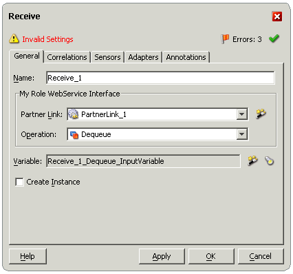
Select the Partner Link corresponding to the partner link configured with the outbound XML Gateway map.
The Dequeue Operation is automatically selected if the partner link has been configured with an outbound XML Gateway map.
The next task is to specify a Variable to receive the message data from the partner link. Click the Create icon to the right of the Variable field. The Create Variable dialog box is displayed. Figure 6-37 shows the Create Variable dialog box.
Figure 6-37 Creating a Variable to Receive Message Data
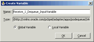
Type a Name for the variable. You can also accept the default name. Click OK.
Click Apply in the Receive dialog box. Click OK.
|
Note: You can define a Header Variable under the Adapters tab of the Receive dialog box. This header variable is populated with context information from the outbound XML message. Values for fields likeMESSAGE_TYPE, MESSAGE_STANDARD and trading party information like PARTY_SITE_ID are returned through this variable.
|
After deploying the BPEL process, you can compile, deploy and test it. In Oracle Applications, you can check for outbound transactions that have been processed by the XML Gateway and delivered to the Transaction Agent, by using the Transaction Monitor. You can also use the Transaction Monitor to resend an outbound document, if necessary. Chapter6, "Run-Time Steps for XML Gateway Inbound into Oracle Applications" discusses the Transaction Monitor.
|
See Also: Oracle XML Gateway User's Guide for details on using the Transaction Monitor. This guide is a part of the Oracle Applications documentation library. Oracle Applications documentation can be accessed from the following link:
|
If you have used a file adapter to write outbound messages from Oracle Applications to files, then you can check the output directory location for the presence of these files after the BPEL process has run.