Sludge Disposal & Design Examples - 01...

General Considerations...

Sludge, or residual solids, is the end product of wastewater treatment, whether biological or physical/chemical treatment. Primary sludge is from 3 to 6 percent solids. Treatment objectives are reduction of the sludge and volume, rendering it suitable for ultimate disposal. Secondary objectives are to utilize the generated gas if anaerobic digestion is selected as part of the sludge managment strategy. In addition, an attempt should be made to sell/utilize the sludge as a soil conditioner rather than paying to dispose of it.

Sludge Pumping...

Sludges with less than 10 percent solids can be pumped through force mains. Sludges with solids contents less than 2 percent have hydraulic characteristics similar to water. For solids contents greater than 2 percent, however, friction losses are from 1 1 / 2 to 4 times the friction losses for water. Both head losses and friction increase with decreasing temperature. Velocities must be kept above 2 feet per second. Grease content can cause serious clogging, and grit will adversely affect flow characteristics as well. Adequate clean-outs and long sweep turns will be used when designing facilities of these types.

( a ) Piping : Sludge withdrawal piping will not be less than 6 inches in diameter. Minimum diameters for pump discharge lines are 4 inches for plants less than 0.5 million gallons per day and 8 inches for plants larger than 1.0 million gallons per day. Short and straight pipe runs are preferred, and sharp bends and high points are to be avoided. Blank flanges and valves should be provided for flushing purposes.

( b ) Pumps : Sludge pumps will be either plunger, progressing-cavity, torque-flow, or open-propeller centrifugal types. Plunger and progressing-cavity pumps generally should be used for pumping primary sludges; centrifugal pumps are more suitable for the lighter secondary sludges. Centrifugal and torque-flow pumps are used for transporting digested sludge in most cases; plunger and progressing-cavity pumps are used when a suction lift is involved. Plunger pumps are also well suited to sludge elutriation. Standby pumps are required for primary and secondary sludge pumps as well as for sludge elutriation pumps. The pump information provided is for guidance only and does not represent design criteria.

( 1 ) Plunger. The advantages of plunger pumps may be listed as follows :

— Pulsating action tends to concentrate the sludge in the hoppers ahead of the pumps.
— They are suitable for suction lifts of up to 10 feet and are self-priming.
— Low pumping rates can be used with large port openings.
— Positive delivery is provided unless some object prevents the ball check valves from seating.
— They have constant but adjustable capacity regardless of large variations in pumping head.
— Large discharge heads may be provided for.
— Heavy-solids concentrations may be pumped if the equipment is designed for the load conditions.

Plunger pumps come in simplex, duplex, triplex models with capacities of 40 to 60 gallons per minute per plunger, and larger models are available. Pump speeds will be between 40 and 50 revolutions per minute, and the pumps will be designed for a minimum head of 80 feet since grease accumulations in sludge lines cause a progressive increase in head with use. Capacity is decreased by shortening the stroke of the plunger; however, the pumps seem to operate more satisfactorily at, or near, full stroke. For this reason, many pumps will be provided with variable-pitch, vee-belt drives for speed control of capacity.

( 2 ) Progressing-cavity. The progressing-cavity pump can be used successfully, particularly on concentrated sludge. The pump is composed of a single-threaded rotor that operates with a minimum of clearance in a double-threaded helix of rubber. It is self-priming at suction lifts up to 28 feet, is available in capacities up to 350 gallons per minute, and will pass solids up to 1.125 inches in diameter.

( 3 ) Centrifugal. With centrifugal pumps, the objective is to obtain a large enough pump to pass solids without clogging but with a small enough capacity to avoid pumping a sludge diluted by large quantities of the overlying sewage. Centrifugal pumps of special design can be used for pumping primary sludge in large plants (greater than 2 million gallons per day). Since the capacity of a centrifugal pump varies with the head, which is usually specified great enough so that the pumps may assist in dewatering the tanks, the pumps have considerable excess capacity under normal conditions. Throttling the discharge to reduce the capacity is impractical because of frequent stoppages, hence it is absolutely essential that these pumps be equippped with variable-speed drives. Centrifugal pumps of the bladeless impeller type have been used to some extent and in some cases have been deemed preferable to either the plunger or screw-feed types of pumps. Bladeless pumps have approximately one-half the capacity of conventional non-clog pumps of the same nominal size and consequently approach the hydraulic requirements more closely. The design of the pump makes clogging at the suction of the impeller almost impossible.

( 4 ) Torque-flow. This type of pump, which uses a fully recessed impeller, is very effective in conveying sludge. The size of the particles that can be handled is limited only by the diameter of the suction or discharge valves. The rotating impeller develops a vortex in the sludge so that the main propulsive force is the liquid itself.

( 5 ) Pump application. Types of sludge that will be pumped include primary, chemical, trickling-filter and activated, elutriated, thickened, and concentrated. Scum that accumulates at various points in a treatment plant must also be pumped.

( 6 ) Primary sludge. Ordinarily, it is desirable to obtain as concentrated a sludge as practicable from primary tanks. The character of primary raw sludge will vary considerably depending on the characteristics of the solids in the wastewater, the types of units and their efficiency, and, where biological treatment follows, the quantity of solids added from the following :

— Overflow liquors from digestion tanks;
— Waste activated sludge;
— Humus sludge from settling tanks following trickling filters; and
— Overflow liquors from sludge elutriation tanks.

The character of primary sludge is such that conventional non-clog pumps will not be used. Plunger pumps may be used on primary sludge. Centrifugal pumps of the screw-feed and bladeless type, and torque-flow pumps may also be used.

( 7 ) Chemical precipitation sludge. Sludge from chemical precipitation processes can usually be handled in the same manner as primary sludge.

( 8 ) Trickling-filter and activated sIudge. Sludge from trickling filters is usually of such homogeneous character that it can be easily pumped with either plunger or non-clog centrifugal pumps. Return activated sludge is dilute and contains only fine solids so that it may be pumped readily with non-clog centrifugal pumps which must operate at slow speed to help prevent the flocculent character of the sludge from being broken up.

( 9 ) Elutriated, thickened, and concentrated sludge. Plunger pumps may be used for concentrated sludge to accommodate the high friction head losses in pump discharge lines. The progressing-cavity type of positive displacement pump also may be used for dense sludges containing up to 20 percent solids. Because these pumps have limited clearances, it is necessary to reduce all solids to small size.

( 10 ) Scum pumping. Screw-feed pumps, plunger pumps, and pneumatic ejectors may be used for pumping scum. Bladeless or torque-flow centrifugal pumps may also be used for this service.

( c ) Controls : The pumping of sludges often requires operation at less than the required design capacity of the pump. For small treatment plants, the design engineer will evaluate the use of a timer to allow the operator to program the pump for on-off operation. For large treatment plants, the use of variable speed controls should be investigated.

Example...

Estimate for a 10 % solids, digested, plain - sedimentation sludge and a velocity of 2 fps ; ( 1 ) the loss of head in 100 ft of 12 in pipe and ( 2 ) the expected range of laminar flow.

( 1 ) Assuming that ( ITA / RO ) is 5 x 10 - 4 sq ft per sec and ( TO / RO ) is 8 x 10 - 3 sq ft per sq sec ;

( h / l ) = ( 32 / g ) ( v / d 2 ) [ ( ITA / RO ) + ( 1 / 6 ) ( TO / RO ) ( d / v ) ]

h = ( 32 / 32.2 ) ( 2 / 1 ) ( 100 ) [ ( 5 x 10 - 4 ) + ( 1 / 6 ) ( 8 x 10 - 3 ) ( 1 / 2 ) ] = 0.23 ft

( 2 )At v P = ( 5 x 10 - 4 + [ ( 1 / 6 ) ( 8 x 10 - 3 ) ] / ( v )

and Re = 2,000

Re = 2,000 = ( v ) / ( v P )

v = 2.2 fps

Sludge Thickening...

Thickening is provided to reduce the volume of sludge. Two basic types of thickeners work by gravity or flotation and use either continuous or batch processes. Gravity thickeners are essentially settling tanks with or without mechanical thickening devices (picket fence type). Plain settling tanks can produce solids contents in sludges of up to 8.0 percent for primary sludges and up to 2.2 percent for activated sludge. Activated sludge can also be concentrated by resettling in primary settling tanks.

Gravity Thickeners...

A gravity thickener will be designed on the basis of hydraulic surface loading and solids loading. The design principles are to be the same as those for sedimentation tanks, as discussed before. Bulky sludges with a high Sludge Volume Index (SVI) require lower loading rates. The use of chemical additives (lime or polyelectrolytes) also allows higher loading rates. The minimum detention time and the sludge volume divided by sludge removed per day (which represents the time sludge is held in the sludge blanket) is usually less than two days. Table shown below gives mass loadings to be used for designing gravity thickeners.

Type of sludge Mass loading ( lb / ft 2 . day )
Primary sludge 22
Primary and trickling filter sludge 15
Primary and waste activated sludge 6 - 10
Waste activated sludge 4 - 8

Flotation Thickening...

Flotation thickening causes sludge solids to rise to the surface where they are collected. This is accomplished by using a dissolved air flotation process. The process is best suited to activated sludge treatment where solids contents of 4 percent or higher are obtained. Table given below provides design values for flotation thickening. This process will generally not be applicable in the size of plants used by the military because of the increased operator attention which it requires. Therefore, this process will not be used at military installations without demonstrated economic advantage with life cycle costs.

Parameter Typical value
Air pressure ( psig ) 40 - 70
Effluent recycle ratio ( % of influent flow ) 30 - 150
Detention time ( hr ) 3
Air : solids ratio ( lb / lb ) 0.02
Solids loading ( lb / ft 2 . day ) 10 - 50
Polymer addition ( lb / ton dry solids ) 10

Sludge Conditioning...

Chemical Conditioning...

Chemical additives may be used to improve sludge dewaterability by acting as coagulants. Chemicals commonly used for this are ferric chloride (FeCl 3 ), lime (CaO), and organic polymers. The application of chemical conditioning is very dependent on sludge characteristics and operating parameters; therefore, a treatability study will be used to determine specific design factors such as chemical dosages. Nevertheless, table given below provides a range of dosages which are typical for various sludge types.

Description Fresh solids Digested
FeCl 3 CaO FeCl 3 CaO
Primary 1 - 2 6 - 8 1.5 - 3.5 6 - 10
Primary and trickling filter 2 - 3 6 - 8 1.5 - 3.5 6 - 10
Primary and waste activated 1.5 - 2.5 7 - 9 1.5 - 4.0 6 - 12
Waste activated ( alone ) 4 - 6 - - -

Physical Conditioning...

Physical conditioning is primarily by heat. Heat conditioning involves heating at 350 to 390 degrees Fahrenheit for 30 minutes at 180 to 210 pounds per square inch gauge. Dewaterability is improved dramatically and pathogens are destroyed as well. The main disadvantage is the return of high biochemical oxygen demand loading to the wastewater stream.

Sludge Dewatering...

Dewatering reduces the moisture content of the sludge so that it can more easily be disposed of by landfill, incineration, heat drying, composting or other means. The objective is a moisture content of 60 to 80 percent, depending on the disposal method. EPA Manual 625/1-82-014 provides information on the capabilities of the various dewatering devices and a methodology for selecting the cost-effective device. Because all dewatering devices are dependent upon proper sludge conditioning, a carefully designed chemical feed system should be included as part of the dewatering facility.

Belt Press Filtration...

Belt filter presses employ single or double moving belts to continuously dewater sludges through one or more stages of dewatering. All belt press filtration processes include three basic opera-tional stages: chemical conditioning of the feed sludge; gravity drainage to a non-fluid consistency; shear and compression dewatering of the drained sludge. When dewatering a 50:50 mixture of anaerobically digested primary and waste activated sludge, a belt filter press will typically produce a cake solids concentration in the 18-23 percent range.

Physical Description...

Figure given below depicts a simple belt press and shows the location of the three stages. Although present-day presses are usually more complex, they follow the same principle indicated in figure given below. The dewatering process is made effective by the use of two endless belts of synthetic fiber. The belts pass around a system of rollers at constant speed, and perform the function of conveying, draining and compressing. Many belt presses also use an initial belt for gravity drainage in addition to the two belts in the pressure zone.

Process Description...

Good chemical conditioning is very important for successful and consistent performance of the belt filter press. A flocculant (usually an organic polymer) is added to the sludge prior to its being fed to the belt press. Free water drains from the conditioned sludge in the gravity drainage stage of the press. The sludge then enters a two-belt contact zone where a second, upper belt is gently set on the forming sludge cake. The belts, with the captured cake between them, pass through rollers of generally decreasing diameter. This stage subjects the sludge to continuously increasing pressures and shear forces. Pressure can vary widely by design, with the sludge in most presses moving from a low pressure section to a medium pressure section. Some presses include a high pressure section which provides additional dewatering Progressively more and more water is expelled throughout the roller section to the end where the cake is discharged. A scraper blade is often employed for each belt at the discharge point to remove cake from the belts. Two spray-wash belt cleaning stations are generally provided to keep the belts clean. Typically, secondary effluent can be used as the water source for the spray-wash. High pressure jets can be equipped with a self-cleaning device used to continuously remove any solids which may tend to plug the spray nozzles.

Performance Variables...

Belt press performance is measured by the percent solids of the sludge cake, the percent solids capture, the solids and hydraulic loading rates, and the required polymer dosage. Several machine variables including belt speed, belt tension and belt type influence belt press performance.

Advantages and Disadvantages...

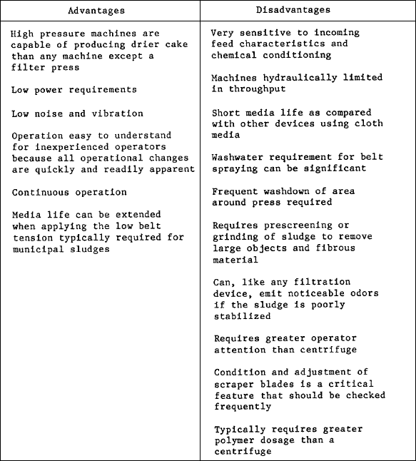
Table given below lists some of the advantages and disadvantages of the belt filter press compared to other dewatering processes.

Design Shortcomings...

Common design shortcomings associated with belt filter press installations and their solutions are listed in table given in below.

Sludge Drying Beds...

Sludge drying beds rely on drainage and evaporation to effect moisture reduction. These beds are open; and, as such, are very susceptible to climatic conditions such as precipitation, sunshine, air temperature, relative humidity, and wind velocity. For example, sludge drying in 6 weeks in summer would take at least 12 weeks to dry in the winter. Sludge bed drying efficiency can be improved significantly by covering the bed with glass or plastic and by providing artificial heat. Heat could be supplied using waste biogas as a fuel or waste heat from the base power plant. Figure given below illustrates a typical bed.

Design Factors...

Area requirements can be interpreted in terms of the per capita values in table given below. These values are very arbitrary and depend largely on climatic conditions. Embankment heights will be 12 to 14 inches, using concrete or concrete-block walls. Underdrains are to be provided with lateral tiles 12 feet apart, and their transported leachate must be returned to the head of the treatment plant. An 8-18 inch bed of gravel, ranging in size from 0.1 to 1.0 inches, is placed on the underdrains. The sand placed on the gravel will have a depth of 18 inches, with the sand being washed and dirt-free. The sand will have an effective size between 0.3 and 0.75 millimeters, with a uniformity coefficient of not more than 4.0. Sludge distribution can be of various design, although an impervious splash plate of some kind is always provided. Sludge cake removal can be by hand or mechanical means. Bed widths may range from 15 to 25 feet, with lengths of 50 to 150 feet. if polymers are added for conditioning, the bed length can be reduced to 50-75 feet to prevent poor sludge distribution on the bed. Multiple beds provide operational flexibility and will be used if appropriate. Enclosed beds will have sides no higher than 18 inches so as not to shade the sludge. Open sides, forced ventilation and artificial heating are possible modifications. Usually, a combination of open and closed beds performs best in average situations. Odor and insects can be a problem unless the sludge is digested completely. Land requirements and sludge cake removal costs are other disadvantages.

Type of sludge Open beds Covered beds
Primary digested 1.5 1.0
Primary and trickling filter digested 1.75 1.25
Primary and activated sludge digested 2.5 1.5
Primary and chemically precipitated sludge digested 2.5 1.5

Vacuum Filtration...

Vacuum filtration reduces sludge moisture content by applying a vacuum (10 to 25 inches mercury) through a sludge layer, using various equipment configurations. Vacuum filters can be drum type, belt type, string discharge type or coil type. The use of coagulant pretreatment is necessary for good dewatering efficiencies. FeCl 3 is the coagulant aid most commonly used. Generally, the higher the feed solids concentration, the higher the filtration rate and filter yield. Feed solids, however, will be limited to 8 to 10 percent to prevent difficulties in handling the sludge. Figure given below shows typical vacuum filter applications.

Filter Yields...

Filter yields vary from 2 to 15 pounds per square foot per hour for various types of sludge. Vacuum filters for digested activated sludge will be designed for a yield of 2 pounds per square foot per hour; while vacuum filters for raw primary sludge will be designed for a filter yield of 10 pounds per square foot per hour. The design filter area will be for the peak sludge removal rate required plus 15 percent area allowance for maintenance downtime. It will be assumed that the filter units will be operated 30 hours per week.

Filter Sizes and Equipment...

Filter sizes cover a wide range and can be up to 12 feet in diameter, with filtering areas up to 700 square feet. Vacuum filtration units are normally supplied with essential auxiliary equipment from various manufacturers.

Disposal of Filtrate...

Dewatering liquids will be returned to the head of the treatment plant. For this reason, the solids concentrations of a vacuum filtrate must be kept as low as practical and can be assumed to be about 10 percent.