Sludge Disposal & Design Examples - 02...
Centrifugation...
Centrifugal dewatering of sludge is a process which uses the force developed by fast rotation of a cylindrical drum or bowl
to separate the sludge solids from the liquid. In the basic process, when a sludge slurry is introduced to the centrifuge,
it is forced against the bowl's interior walls, forming a pool of liquid. Density differences cause the sludge solids and
the liquid to separate into two distinct layers. The sludge solids "cake" and the liquid "centrate" are then separately
discharged from the unit. The two types of centrifuges used for municipal sludge dewatering, basket and solid bowl, both
operate on these basic principles. They are differentiated by the method of sludge feed, magnitude of applied centrifugal
force, method of solids and liquid discharge, cost, and performance.
Basket Centrifuge...
The imperforate basket centrifuge is a semi-continuous feeding and solids discharging unit that rotates about a vertical
axis. A schematic diagram of a basket centrifuge in the sludge feed and sludge plowing cycles is shown in figure given
below. Sludge is fed into the bottom of the basket and sludge solids form a cake on the bowl walls as the unit rotates. The
liquid (centrate) is displaced over a baffle or weir at the top of the unit. Sludge feed is either continued for a preset
time or until the suspended solids in the centrate reach a preset concentration. The ability to be used either for
thickening or dewatering is an advantage of the basket centrifuge. A basket centrifuge will typically dewater a 50:50 blend
of anaerobically digested primary and waste activated sludge to 10-15 percent solids.
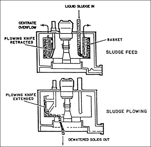
( a ) Process Description : After sludge feeding is stopped, the centrifuge begins to decelerate and a special
skimmer nozzle moves into position to skim the relatively soft and low solids concentration sludge on the inner periphery
of the sludge mass. These skimmings are typically returned to the plant headworks or the digesters. After the skimming
operation, the centrifuge slows further; to about 70 revolutions per minute, and a plowing knife moves into position to cut
the sludge away from the walls; the sludge cake then drops through the open bottom of the basket. After plowing terminates,
the centrifuge begins to accelerate and feed sludge is again introduced. At no time does the centrifuge actually stop
rotating.
( b ) Application : The cake solids concentration produced by the basket machine is typically not as dry as that
achieved by the solid bowl centrifuge. However, the basket centrifuge is especially suitable for dewatering biological or
fine solids sludges that are difficult to dewater, for dewatering sludges where the nature of the solids varies widely, and
for sludges containing significant grit. The basket centrifuge is most commonly used for thickening waste activated sludge.
A basket centrifuge can be a good application in small plants with capacities in the range of 1 to 2 million gallons per day
where thickening is required before or after stabilization or where dewatering to 10 to 12 percent solids is adequate. The
basket centrifuge is sometimes used in larger plants.
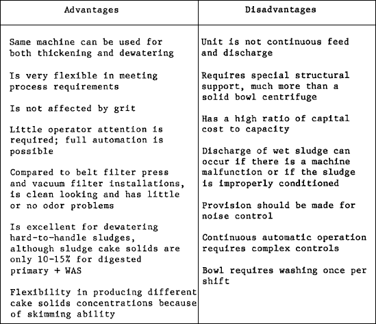
( c ) Advantages and Disadvantages : Advantages and disadvantages of a imperforate basket centrifuge compared to
other dewatering processes are presented in table given below.
( d ) Design Shortcomings : Common design shortcomings experienced in basket centrifuge installations and their
solutions are presented in table given below.
 Solid Bowl Centrifuge...
Solid bowl centrifuge technology has greatly advanced in the past five to six years, as both the conveyor life and machine
performance have been improved. At many treatment plants in the U.S., older solid bowl centrifuge installations have
required very high maintenance expense due to rapid wear of the conveyor and reduced performance. Recently the use of
replaceable ceramic tile in low-G centrifuges (<1, 100 Gs) and sintered tungsten carbide tile in high-G centrifuges (>1, 100
Gs) have greatly increased the operating life prior to overhaul. In addition, several centrifuge manufacturers also offer
stainless steel construction in contrast to carbon-steel construction, and claim use of this material results in less wear
and vibration caused by corrosion. Revised bowl configurations and the use of new automatic backdrives and eddy current
brakes have resulted in improved reliability and process control, with a resultant improvement in dewatering performance.
Also in recent years, several centrifuge manufacturers have reduced the recommended throughput of their machines in direct
response to competition from the belt filter press. This has allowed for an increase in solids residence time in the
centrifuge and subsequent improvement in cake dryness.
( a ) Physical Description : As opposed to the semi-continuous feed/discharge cycles of the imperforate basket
centrifuge, the solid bowl centrifuge (also called decanter or scroll centrifuge) is a continuously operating unit. This
centrifuge, shown in figure given below, consists of a rotating, horizontal, cylindrical bowl containing a screw-type
conveyor or scroll which rotates also, but at a slightly lower or higher speed than the bowl. The differential speed is the
difference in revolutions per minute (rpm) between the bowl and the conveyor. The conveying of solids requires that the
screw conveyor rotate at a different speed than the bowl. The rotating bowl, or shell, is supported between two sets of
bearings; and at one end, necks down to a conical section that acts as a dewatering beach or drainage deck for the
screw-type conveyor. Sludge enters the rotating bowl through a stationary feed pipe extending into the hollow shaft of the
rotating conveyor and is distributed through ports in this hollow shaft into a pool within the rotating bowl.
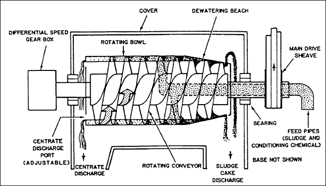
( b ) Countercurrent Centrifuge : The centrifuge illustrated in figure given above operates in the countercurrent
mode. Influent sludge is added through the feed pipe; under centrifugal force, sludge solids settle through the liquid to
the bowl wall because their density is greater than that of the liquid. The solids are then moved gradually by the rotating
conveyor from left to right across the bowl, up the dewatering beach to outlet ports and from there drop downward into a
sludge cake discharge hopper. As the settled sludge solids move from left to right through the bowl toward the sludge cake
outlet, progressively finer solids are settled centrifugally to the rotating bowl wall. The water or centrate drains from
the solids on the dewatering beach and back into the pool. Centrate is actually moved from the end of the feed pipe to the
left, and is discharged from the bowl through ports on the left end, which is the opposite end of the centrifuge from the
dewatering beach. The loca-tion of the centrate removal ports is adjustable and their location establishes the depth of
the pool in the bowl.
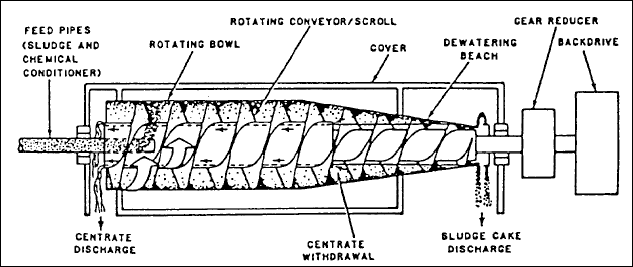
( c ) Concurrent Centrifuge : A second variation of the solid bowl centrifuge is the concurrent model shown in
figure given below. In this unit, liquid sludge is introduced at the far end of the bowl from the dewatering beach, and
sludge solids and liquid flow in the same direction. General construction is similar to the countercurrent design except
that the centrate does not flow in a different direction than the sludge solids. Instead, the centrate is withdrawn by a
skimming device or return tube located near the junction of the bowl and the beach. Clarified centrate then flows into
channels inside the scroll hub and returns to the feed end of the machine where it is discharged over adjustable weir
plates through discharge ports built into the bowl head.
( d ) Differential Speed Control : A relatively new development in solid-bowl decanter centrifuges is the use of a
backdrive to control the speed differential between the scroll and the bowl. The objective of the backdrive is to control
the differential to give the optimum solids residence time in the centrifuge and thereby produce the optimum cake solids
content. a backdrive of some type is considered essential when dewatering secondary sludges because of the fine particles
present. The backdrive function can be accomplished with a hydraulic pump system, an eddy current brake, direct current
variable speed motor or a Reeves-type variable speed motor. The two most common backdrive systems are the hydraulic
backdrive and the eddy current brake.
( e ) Installation : Most centrifuge installations have the centrifuge mounted a few feet above the floor and use a
belt conveyor to move dewatered cake away. Other methods of installing a solid bowl centrifuge are to put the centrifuge on
the second floor of a two-story building and drop the dewatered cake into either trucks or a storage hopper on the first
level; to mount the centrifuge about a foot off the floor and to drop cake onto a screw conveyor built into the floor; or to
let the centrifuge cake drop into an open-throated, progressive cavity-type pump for transfer of the cake to a truck,
incinerator or storage.
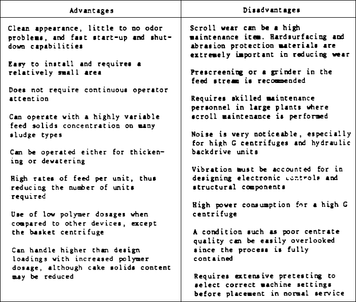
( f ) Advantages and Disadvantages : Some of the advantages and disadvantages of a solid-bowl decanter centrifuge
compared with other dewatering processes are presented in table given below. The ability to be used for thickening or
dewatering provides flexibility and is a major advantage of solid bowl centrifuges. For example, a centrifuge can be used
to thicken ahead of a filter press, reducing chemical usage and increasing solids throughput. During periods of downtime of
the filter press, the solid bowl centrifuge can serve as an alternate dewatering device. Another advantage of the solid bowl
centrifuge for larger plants is the availability of equipment with the largest sludge throughput capability for single units
of any type of dewatering equipment. The larger centrifuges are capable of handling 300 to 700 gallons per minute per unit,
depending on the sludge's characteristics. The centrifuge also has the ability to handle higher-than-design loadings, such
as a temporary increase in hydraulic loading or solids concentration, and the percent solids recovery can usually be
maintained with the addition of more polymer (while the cake solids concentration will drop slightly, the centrifuge will
stay online). Solid bowl centrifuges are typically capable of dewatering a 50:50 mixture of anaerobically digested primary
and secondary sludges to a 15-21 percent solids concentration. Table given below lists common design shortcomings and their
solutions.
 Filter Presses...
The plate-and-frame press is a batch device that has been used to process difficult to dewater sludges. Recent improvements
in the degree of automation, filter media and unit capacities have led to renewed interest in pressure filtration for
application to municipal-type sludges. The ability to produce a very dry cake and clear filtrate are major points in favor
of pressure filtration, but they have higher capital and operating costs than vacuum filters. Their use in preference to
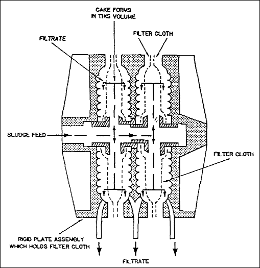
vacuum filters will be acceptable providing they can be economically justified. Figure given below illustrates a
cross-section of a filter press.
( a ) Control : Control of filter presses may be manual, semi-automatic, or full automatic. Labor requirements
for operation will vary dramatically depending on the degree of instrumentation utilized for control. In spite of
automation, operator attention is often needed during the dump cycle to insure complete separation of the solids from the
media of the filter press. Process yields can typically be increased 10 to 30 percent by carefully controlling the optimum
cycle time with a microprocessor. This is important since the capital costs for filter presses are very high.
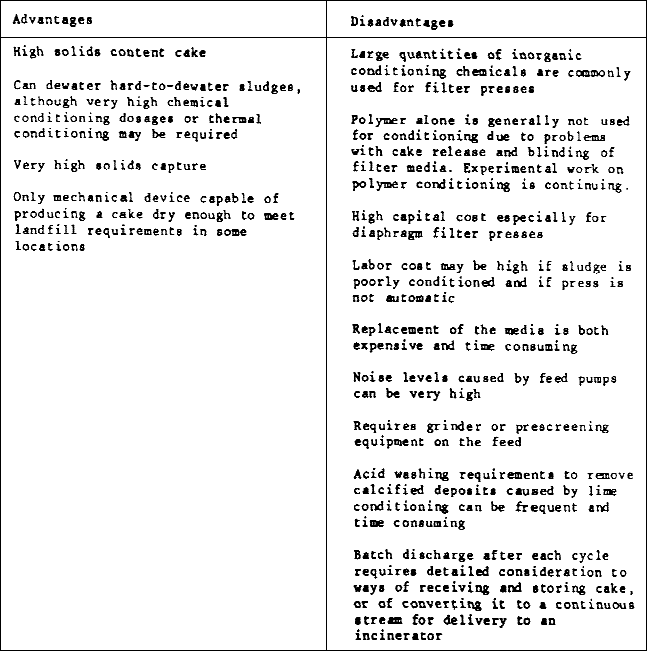
( b ) Advantages and Disadvantages : Table given below presents the principal advantages and disadvantages of filter
presses compared to other dewatering processes. Common design shortcomings associated with filter press installations are
listed in table given below along with solutions for these shortcomings. The fixed volume, recessed plate filter press will
typically dewater a 50:50 blend of digested primary and waste activated sludge to between 35-42 percent solids, while a
diaphragm press will produce a 38-47 percent solids cake on the same sludge. These cake solids concentrations include large
amounts of inorganic conditioning chemicals.
 Aerobic Sludge Digestion...
The major function of sludge digestion (and its principal advantage) is the stabilization of the sludge in terms of
volatile content and biological activity. Aerobic digestion accomplishes this through biological oxidation of cell matter
which is done without the production of volatile solids or high biochemical oxygen demand liquor associated with anaerobic
digestion.
( a ) Modes of Operation : Aerobic digesters can be either continuous or intermittent batch operations. With batch
operation, waste sludge feed will be discontinued at a specified time before digested sludge withdrawal. In continuous
operation, supernatant is constantly withdrawn. This mode of operation is used when phosphorus is a problem and low
phosphorus levels are required in the effluent because batch operation produces high phosphorus concentrations in the
supernatant.
( b ) Design Factors : A summary of design factors is given in table shown below. The tank is open, which can be a
problem in cold climates with mechanical aeration; no heating is required although some increase in volatile solids
reduction can be obtained with increased temperature. Tank design is similar to aeration basin design with the addition of
a sludge thickening apparatus. A major disadvantage of aerobic digestion is the high energy requirement.
 Anaerobic Sludge Digestion...
( a ) Process Description : Anaerobic sludge digestion is the destruction of biological solids using bacteria which
function in the absence of oxygen. This process produces methane gas which can be used as an energy source and can make
anaerobic digestion more economically attractive than aerobic digestion. The larger the treatment plant, the greater the
economic incentive to use anaerobic digestion. However; anaerobic digestion is considerably more difficult to operate than
aerobic digestion. The methane produced could be of great benefit in cold regions as a supplemental source of heat.
Therefore, the decision to use anaerobic digestion must carefully evaluate the operational capability of the
installation.
( b ) Objectives : The objectives of anaerobic digestion are the stabilization of organic solids, sludge volume
reduction, odor reduction, destruction of pathogenic organisms, useful gas production, and the improvement of sludge
dewaterability. Volatile solids typically are reduced by 60 to 75 percent, with final volatile matter contents of 40 to 50
percent.
( c ) Conventional ( Standard - Rate) Digestion Systems : This type of system will consist of a single or two-stage
process for which tanks will provide for digestion, supernatant separation, and concentration under the following loadings.
Two-stage processes are more applicable for plants having capacities of more than 1 million gallons per day. The retention
period in the first stage tank will be 8 days and 22 days in the second stage tank. The minimum total retention time will
be 30 days if the tank is heated to 95 degrees Fahrenheit. Unit capacities required for separate unheated tanks will be
increased in accordance with local climatic conditions but not less than twice the value indicated for each of the three
sludge sources in table given below.

( d ) High - Rate Digestion : The high-rate digestion process differs from the standard-rate process in that the
solids loading rate is much greater (up to 4 times). The retention period is lower (one-half), mixing capacity is greater
and improved, and the sludge is always heated. High-rate tanks will be those where the digestion process (accomplished
separately from supernatant separation, and sludge concentration and storage) includes rapid and intimate mixing of raw and
digesting sludge in the entire tank contents with an operating temperature of 95 degress Fahrenheit. The process will be a
two-stage system applicable for treatment plants with capacities greater than 1 million gallons per day and with the primary
digestion tank considered the high-rate tank. If sludge drying beds or ponds are to be used for dewatering of the digested
sludge, the retention time of the solids in the primary digester will be 15 days. If mechanical sludge dewatering processes
are employed, the retention time in the primary digester may be reduced to 10 days. The secondary digester must be of
sufficient capacity to provide for supernatant separation and storage of digested sludge. The primary digestion tanks will
be sized to provide 75 percent of the total design tank volume (table given below).

( e ) pH Control : The pH level of the sludge inside the digester is a critical factor in anaerobic digestion and
will be kept as near to 7.0 as possible, with a range of 6.6 to 7.4 considered acceptable. Also, monitoring of the volatile
acids-to -alkalinity ratio is important. The pH is maintained with bicarbonate buffering and, when natural buffering fails
and the pH becomes less than 6.6, hydrated lime (calcium hydroxide) should be added to the digester. Design provisions must
be made that will provide a simple means for adding lime to the digester if and when needed. One of the more practical means
is to provide for convenient manual addition of lime to the raw sludge pit before the raw sludge is pumped to the digester.
Tank Element Design...
( a ) Tank Dimensions : No particular shape possesses advantages over all others but circular tanks are more popular.
Circular tanks will not be less than 20 feet or more than 100 feet in diameter. Side-wall water depths will be a minimum of
20 feet and a maximum of 30 feet. A 2.5 feet freeboard will be provided between the top of the wall and the working liquid
level. With mechanisms for removing sludge, the bottoms of the tanks will be flat; overwise, hopper bottoms with steep
slopes of 3 feet horizontal to 1 foot vertical will be provided. All tanks designed for treatment plants rated at or above
1.0 million gallons per day will be multiple units.
( b ) Covers : Two types of covers are used on sludge digestion tanks, fixed and floating. If a combination of
covers is used, fixed covers will be used for the primary stage of a two-stage digestion process, and floating covers will
be used for the secondary stage. In lieu of floating covers on separate digesters and in cold regions where freezing ice and
snow are problems, fixed covers may be used provided a gas collection dome is installed in the top of the cover. At least
two access manholes will be provided in the tank roofs. In addition, the tank covers will be provided with sampling wells,
pressure and vacuum relief valves, and flame traps.
( c ) Control Chamber : Entrance to the control chamber must be designed with the safety of the operator and the
equipment foremost. The chamber will be well-lighted, ventilated, and equipped with a water service and drain. All
sludge-heating equipment, gas piping, gas meters, controls and appurtenances will be located in a separate structure.
All the above-mentioned structures will be of explosion-proof construction.
( d ) Piping : The particular piping requirements for sludge digesters will include provisions for adding sludge,
withdrawing sludge, multi-level supernatant removal points, heating, recirculating sludge or supernatant, flushing, sampling
gas collection, and gas recirculating. All supernatant will be returned to process for further treatment. Supernatant
draw-off facilities will be designed to provide variable-rate return to prevent plant upset.
( e ) Heating : The method to be used for heating sludge digestion tanks is the circulation of the contents of the
tank through a heat exchanger. Heated tanks will be insulated and the heating equipment sized to maintain a temperature of
95 degrees Fahrenheit during the coldest weather conditions.
( f ) Chemical Feeding : Practical means for feeding lime or other chemicals that are commonly used to correct
digester operation problems must be included as part of the digester design.
( g ) Gas Collection : Sludge gas will be collected from the digesters either for utilization or for burning it to
waste. Two-stage units will provide interconnecting lines, permitting transfer and storage from one unit to the other. Gas
withdrawal will be from a common point.
( h ) Gas Utilization : Gas storage facilities will have to be provided if the gas is to be utilized and not wasted
by burning. Sludge gas has a heat value of between 500 and 700 British thermal units per cubic foot. An average gas yield
is 15 cubic feet per pound of volatile solid destroyed.
Example...
Data...
Waste solids produced by primary sedimentation of municipal wastewater contain 72.2 % volatile matter on a dry basis and
95 % water. During experimental digestion at 30 O C ( 86 O F ) of 384 g of fresh wet solids,
the gas yield is 783 mL / g of volatile solids, 72 % by volume being methane. The wet digested solids, exclusive of the
seeding material, weigh 93 g and contain 87 % water, the volatile matter being 38.2 % on a dry basis.
Questions...
( a ) Cubic feet and pounds of gas per pound of volatile matter destroyed ;
( b ) Net fuel value of the gas in BTU per cubic foot and per pound volatile matter destroyed ;
( c ) Cubic feet of gas per cubic foot of wet solids daily and per capita daily on the assumption that 37.8 cu ft of wet
solids per 1,000 persons are added daily to the digestion unit, and that the daily charge of the digestion unit is
proportional to the batch charge of the experimental unit ;
( d ) Relative volume of gas measured at a temperature of 68 O F and a barometric pressure of 29.6 in.
Solution...
( a ) The weights of volatile matter in the fresh and digested solids are respectively ; [ ( 384 ) ( 100 - 95 ) / ( 100 ) ]
( 72.2 / 100 ) = 13.9 g and [ ( 93 ) ( 100 - 87 ) / ( 100 ) ] ( 38.2 / 100 ) = 4.6 g. Hence the weight of volatile matter
destroyed is ( 13.9 - 4.6 ) = 9.3 g and the volume of gas per gram of volatile matter destroyed becomes ( 783 )
( 13.9 / 9.3 ) = 1,170 mL. Because 1 cu ft = 28.3 L and 1 lb = 454 g, the volume of gas is ( 1.17 ) ( 454 / 28.3 ) = 18.8
cu ft / lb of volatile matter destroyed. The weight of this gas is [ ( 0.0446 ) ( 0.72 ) + ( 0.1225 ) ( 0.28 ) ] ( 18.8 ) =
1.25 lb / lb volatile matter destroyed. This is a well - established value for the digestion of plain - sedimentation
wastewater solids.
( b ) The net fuel value of the gas is ( 963 ) ( 0.72 ) = 690 BTU / cu ft, or ( 18.8 ) ( 690 ) = 13,000 BTU / lb volatile
matter destroyed.
( c ) The gas yield of 783 mL / g of volatile solids equals ( 783 ) ( 0.05 ) ( 0.722 ) = 28.3 mL / g of wet solids. The
specific gravity of the fresh wet solids is 1.010. Therefore, the gas yield is ( 28.3 ) ( 1.010 ) = 28.5 mL / mL or
cu ft / cu ft, and the daily per capita output of gas is [ ( 28.5 ) ( 37.8 ) ] / ( 1,000 ) = 1.08 cu ft. A value of
about 1 cu ft of gas per capita daily is a useful background figure for the gas yield of digesting, plain - sedimentation
wastewater solids.
( d ) By equation ;
V O = ( 16.4 ) ( V ) [ ( p - p W ) / ( 459.7 + T ) ]
Where ; V : volume of the gas and p W : vapor pressure of water.
( V / V O ) = ( 459.7 + 68.0 ) / [ ( 16.4 ) ( 29.6 - 0.7 ) ] = 1.11. The vapor pressure of water at 68
O F being 0.7 in Hg. 1.11 cu ft of gas will be recorded for each cubic foot of gas under standard conditions.
Example...
A cylindrical digester 20 ft in diameter is built of concrete and surrounded by dry earth or provided with equivalent
insulation. The side walls are 16 ft high, and the roof rises 1 ft to a central, insulated gas dome and is exposed to the
air. The bottom slopes 4 ft to a central sludge - withdrawal pipe. The daily weight of sludge added to the tank is 13,000
lb. Find ; ( a ) the daily heat requirements of the tank when the temperatures of the incoming sludge, digesting sludge,
earth, and air are 50, 90, 40, and 20 O F, respectively, and the coefficient of heat flow is 0.20 BTU per sq
ft per hr ; ( b ) the required area of stationary heating coils through which water is circulated at an incoming
temperature of 130 O F and with a temperature drop of 10 O F if the coefficient of heat flow
is 10 BTU per sq ft per hr ; and ( c ) the daily volume of heating water that must be circulated through the coils.
( a ) Heat requirements ;
- The area of the tank exposed to earth is = ( PI ) ( 20 ) { ( 16 ) + [ ( 10 2 + 4 2 ) ]
1 / 2 } = 1,344 sq ft.
- The area of roof exposed to air is = ( PI ) ( 10 ) [ ( 10 2 + 1 2 ) 1 / 2 ] =
316 sq ft.
- Heat requirements of the incoming sludge is = ( 13,000 ) ( 90 - 50 ) = 520,000 BTU per day
- Exposure loss is = ( 0.20 ) ( 24 ) [ ( 1,344 ) ( 90 - 40 ) + ( 316 ) ( 90 - 20 ) ] = 430,000 BTU per day
- Total heat requirements = 520,000 + 430,000 =950,000 BTU per day
( b ) Area of heating coils ;
- Average temperature of heating water = 130 - 5 = 125 O F
- Area of coils = ( 950,000 ) / [ ( 24 ) ( 10 ) ( 125 - 90 ) ] = 113 sq ft
( c ) Recirculating water ;
- Temperature drop = 10 O F = 10 BTU per lb.
- Weight of water = ( 950,000 ) / ( 10 ) = 95,000 lb per day.
- Volume of water = ( 95,000 ) / ( 8.34 ) = 11,400 GPD = 8 GPM.
Sludge Storage...
( a ) Sludge Tanks : Sludge storage tanks may have depths no less than 15 feet and bottom slopes of 1 in 4. The
tanks may be open or closed. Ventilation must be provided with closed tanks. Decanting lines as well as sludge withdrawal
lines must be provided for all tanks.
( b ) Sludge Retention Ponds : Sludge retention facilities will be provided at either the treatment plant or land
application site. The design detention period will be large enough to compensate for periods when sludge spreading is not
feasible but will not be less than 30 days. Storage will permit operation flexibility, additional destruction of pathogens
and further sludge stabilization.
( c ) Sludge Storage Ponds : Sludge storage ponds are applicable for storage of well-digested sludge when land area
is available. Storage is usually long term (2 to 3 years), with moisture content being reduced to 50-60 percent. Lagoon
storage can be used as a continuous operation or can be confined to peak load situations, and serves as a simple and
economical sludge storage technique. Land requirements and possible groundwater pollution are the major disadvantages.


