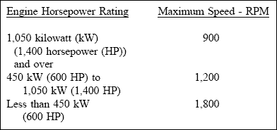
( a ) Cooling systems.
Two basic types of cooling systems are radiator and heat exchanger. Selection criteria include engine size, space availability, raw or sump water supply, initial cost, operation and maintenance cost, and environmental concerns. A radiator system may have the radiator mounted on the engine base or remotely mounted. The radiator will always be located where an adequate supply of cooling air is available. For larger engines, the physical size of the radiator may make it an impractical choice. The selection of the fan and radiator location would include the noise level, heat produced, and size requirements. The heat exchanger cooling system will be the closed type. It can be an elaborate system with raw or canal water supply pumps, a shell and tube heat exchanger, and a traveling water screen (screen the raw water to the supply pumps) to cool the engine’s jacket water. It could also be a simplified submerged pipe type. This type circulates engine jacket water through pipes submerged in the pump sump. Selection will be based on engine cooling requirements and the recommendation of the engine manufacturer. Some problems associated with heat exchanger cooling are freezing climates, foul cooling water, rejecting heated raw water to the canal, and engine testing restrictions when the sump or entering ditch is dry.
( b ) Control equipment.
All engines will be designed for manual starting. Manual and automatic control devices should be of the types regularly furnished by the engine manufacturer for similar service. Automatic engine shutdown is required for engine overspeed. Visual and audible alarms and automatic engine shutdown (as a minimum) should occur for high jacket water temperature, high lubricating oil temperature, low lubricating oil pressure, gear reducer high lubricating oil temperature, or gear reducer low lubricating oil pressure. The type of speed control devices will depend upon the desired scheme of operation, but a governor to maintain speed and a suitable speed indicator should be provided in all cases. Consideration can be given to an engine shutoff method for low sump water elevation. Engine controls are generally located adjacent to the engine. Redundant remote read-out of critical engine, pump, and gear parameters may be located in an operating office for large pumping stations. The control system should be designed so that the engines can be started and operated when the electric power to the station is interrupted and automatic engine shutdown should not occur due to minor fluctuations in commercial power. A control system for engines less than 300 kW (400 HP) rating can be equipped with a rechargeable battery system for its operation. Larger sized engines will require a separate engine-generator to provide electrical power for the control system. The controls should permit operation of the engine’s jacket water pump to allow cool down of the engine if required by the engine manufacturer. If the jacket water pump is engine driven, then an auxiliary motor driven jacket water pump should be considered for cool down, if required. A means needs to be furnished to manually shutoff the intake air supply to the engine to provide for critical shutdown. Crankcase explosion relief valves should be provided for diesel engines.
( c ) Engine equipment and auxiliaries.
(1) Clutches. Engines less than 450 kW (600 HP) may be equipped with a manual clutch mechanism, which allows the engine to be started and operated without running the pump. This permits testing of the engine without regard to water levels that may not allow pump operation.
(2) Flexible drive shafts. Flexible drive shafts eliminate the need for critical alignment of the engine to the gear reducer. The drive shaft consists of a center section with a flexible joint on each end. One of the flexible joints incorporates a splined slip joint that permits longitudinal movement to occur. The drive shaft manufacturer’s published rating at the maximum engine speed should be at least 1-˝ times the maximum torque of the pump that usually occurs at its maximum head condition. A drive shaft minimum length of 900 millimeters (36 inches) is desirable to allow for intentional or accidental misalignment. A vertical difference of approximately 15 millimeters (0.5 inch) (for 900 millimeters (36-inch) shaft length) should be provided between the engine output shaft and the gear input shaft to provide continuous exercise for the flexible joints. There are other types of engine-to-gear connections, such as direct through flexible couplings. This can be investigated if site conditions prevent the use of the drive shaft described above.
(3) Starting system. The engine starting system should be pneumatic except for small engines. The air system should contain a reservoir of sufficient size to permit two starts of each unit without recharge by the air compressor. The time for the air compressor to recharge the reservoir should not exceed 2 hours. Two air compressors should be provided for reliability. Unless a standby generating unit is provided for the station, one of the air compressors should be engine driven so that the air pressure can be built up during electric power outages.
(4) Prelubrication. Engine manufacturer’s should be consulted as to any requirements for a prelubrication pump. Factors that are normally used to determine the need for prelubrication requirements are engine size and the expected period of time between operations.
