Mechanical and Electrical Design of Pumping Stations - 21...
Chapter - 21 : Station Service Electrical System...
21-1. Auxiliary Power Distribution...
( a ) Low-voltage stations.
In low-voltage stations,
auxiliary loads of 480 volts and below are most conveniently
distributed by means of a power panel(s) either
mounted in a vertical section of the motor control center
or in a strategic location along a station wall. This
power panel(s) should be fed from a circuit breaker or
fusible disconnect switch in the motor control center. A
separate auxiliary or lighting service may be required to
obtain the optimum rate schedule from the utility.
( b ) Medium-voltage stations.
In medium-voltage
stations, packaged unit substations are available that
conveniently incorporate a high-voltage load interrupter
switch, a 4160/480-volt transformer section, and a power
panel section. It is not necessary to provide a main
breaker on the power panel since the high-voltage interrupter
switch provides a disconnecting means. Threephase
voltmeters should be provided to monitor the
480-volt service. A separate auxiliary or lighting service
may be required to obtain the optimum rate schedule
from the utility.
21-2. Lighting System...
In general, 208/120-volt, three-phase, four-wire systems
are recommended for lighting loads. A minimum of
20-percent spare circuits should be provided for future
expansion. Operating floor lights, floodlights, and other
lights that may be used for considerable periods of time
should usually be of the high-pressure sodium-type due
to their efficiency. Where possible, several operating
floor fixtures should be furnished with quartz restrike
lamps, automatically switched so that light is available
immediately upon energization or during restrike. If
selected fixtures do not have quartz restrike as an option,
several incandescent fixtures should be provided for this
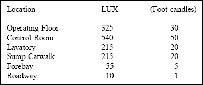
purpose. Following are typical foot-candle levels for
various pumping station areas :