Mechanical and Electrical Design of Pumping Stations - 28...
Chapter - 28 : Appendix D - Closure Gates...
D-1. Purpose...
The purpose of this appendix is to explain the procedure
used in determining the size of gate closure, the stem
size, the operator size, and loads to be carried by the
structure at the gate location (Figures D-1, D-2, and
D-3).
D-2. Gate Size...
The size of gate required is determined using the maximum
pumping capacity of the station and the number of
pumps. The velocity through the gates at the maximum
capacity should be limited to 2.0 feet per second (fps) to
achieve the best flow conditions to the pump when used
for sump closure. The maximum capacity of the station
can be estimated at 33 percent above the design capacity.
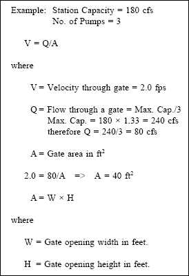
Note : The gate opening height and width are then determined
using the area calculated, the sump floor elevation,
sump width, and the minimum pumping elevation. The
top of the gate opening should not be higher than the
minimum pumping elevation. If this is not possible at a
particular site, then the top of the gate opening should not be higher than the elevation at which all pumps are
operating. For this example use :
 D-3. Type of Gate Operation...
Slide gates can be used for seating and unseating operating
head conditions. Seating head occurs when the level
of the water is greater on the gate side of the wall. This
type of head condition results in the best seal against
leakage. Unseating head occurs when the level of the
water inside the gate is greater than the water outside the
gate. This type of head condition results in a lesser seal
when compared with that achieved with the seating head
condition.
D-4. Gate Operator Size...
( a ) Required force.
The size of the gate operator is
determined by first calculating the force needed to open
the gate with the maximum differential head acting on
the gate. This will normally occur when the sump is dry
and the maximum expected forebay water elevation is
present.
(1) There are three terms used during the selection
of a motorized gate operator: run torque, pullout torque,
and stall torque. The definition of each of these terms is
as follows :
(a) Pullout torque. This is the torque the operator
develops to initially break the seal caused by the wedges
on the sluice gate; operators are designed to develop this
torque for only a short period of time.
(b) Run torque. This is the torque the operator
develops to move the gate after the wedge seal is broken;
operators should be designed to develop this torque
continuously.
(c) Stall torque. This is the torque that is developed
by the operator just as the motor stalls out; this is the
maximum torque which will be exerted on the gate stem.
(2) Example: See Figure D-1 :
Gate centerline - el. 50.0 ft.
Maximum expected forebay water elev. - el. 54.0.
Gate height - 5.0 ft.
Gate width - 8.0 ft.
Operating floor elevation - el. 65.0.
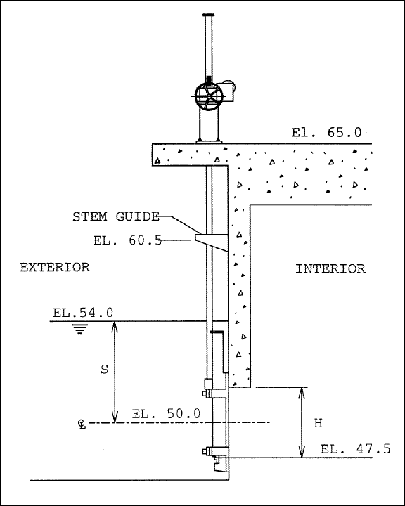
Figure D-1. Sluice gate and operator.
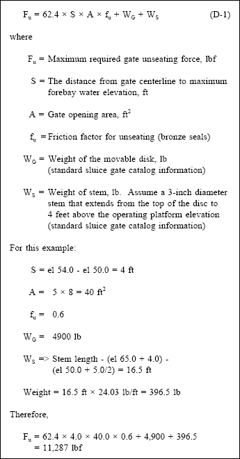
(b) Preliminary hoist and stem size. This force or
thrust to unseat the gate is then compared with manufacturers
of motorized gate operatorsí catalog information to
determine a preliminary hoist and stem size.
( b ) Required torque.
The required torque (ft-lb) is
determined by multiplying the calculated thrust with the
stem factor (provided by manufacturer). For this example
the stem factor is 0.0204 with 3 threads per inch.
The resultant torque = 11,287 ◊ 0.0204 = 230.3 ft-lb.
( c ) Output rotation speed.
The required output rotation
speed of the operator (in rpm) is then determined.
For this example, the desired gate travel speed is approximately
1 foot per minute.
Stem Nut Rotation Speed = (1 ft/min)(12 in/ft)(3 thrd/in) = 36 rpm.
(1) The torque required of 230.3 ft-lb and speed of 36 rpm is used to select an operator.
(2) The electric data for this operator are then obtained from either the catalog or directly from the manufacturers. These
data are used for preparing the electrical design of the station.
D-5. Maximum Loads on Stem...
( a ) Calculation of maximum loads.
The maximum
loads which can be transferred to the stem and the structure
are calculated. The design shall be such that the
stem would fail before any supporting structural failure
would occur. The maximum loads are based on 125 percent
of the stall torque (taken from published catalog
information) of the operator selected.
(1) For this example, the stall torque of the selected
operator is 481 ft-lb (this figure should always be verified
by the gate operator manufacturer).
Max. Thrust = (Stall Torque ◊ 1.25)/Stem Factor = (481 ◊ 1.25)/0.0204 = 29,473 lbf.
(2) The maximum thrust is an upward thrust of
30 kips and a downward thrust of 35 kips (this includes
the dead weight of the gate itself).
(3) The required spacing of the stem guides is then
determined. The Euler Column Formula is used :
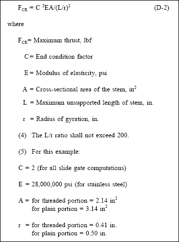
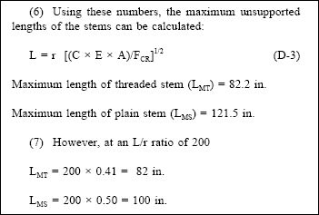
(8) Since both the L/r ratio < 200 and the Eulerís
Column Formula criteria have to be met, the criterion
resulting in the shortest lengths is used. For this example,
the L/r ratio < 200 criterion has resulted in the shortest
lengths. Two stem guides are located to meet these
calculated lengths. Figure D-1 shows that one stem
guide was placed at el 60.5 or 96 inches (8.0 feet) above
the top of the gate (this length of stem is solid; therefore the previously calculated 100-in. maximum length is
applied). The other stem guide would be located at the
bottom of the gate operator base. This location would
result in a length between guides of 54 inches, which is
less than the minimum for threaded stem (82 in.).
( b ) Position limit switches.
All motorized gate operators
shall be equipped with position limit switches in the
open and closed positions. In addition, mechanical
torque limit switches should be provided. These would
provide backup in case the position limit switches fail or
if debris jams the gate while opening or closing.
( c ) Roller gates.
The same computations are done
for roller gates to size the operators and structural design
loads. The force required to open this type of gate is the
sum of gate weight, stem weight, seal friction, and roller
friction. The seal friction is a result of the deflection of
the rubber J-seal attached to the top and sides of the gate.
The roller friction is a result of the bearing friction in the
roller and the roller-to-rail friction. The amount of seal
and roller friction will vary depending on the types of
materials used for the roller wheels, roller bearings, rails
and seal plates.
(1) If the roller gate is extra wide or if the ratio of
the width to the height is equal to or greater than 2:1, the
gates are normally raised and lowered through the use of
two stems placed near each side of the gate. Each stem
passes through a geared operator. The geared operators
are both connected to an electric or hydraulic operator
located between the two stems. The loads incurred by
raising the gate are equally distributed between the two
stems.
(2) During the early design phases of a pump station,
a roller gate manufacturer should be consulted to
assist in determining the design loads, forces, and lifting
arrangement.
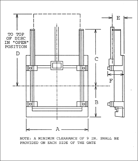
Figure D-2. Sluice gate layout.
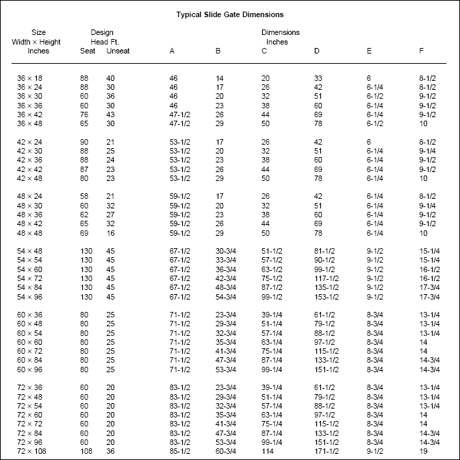
Figure D-3. Typical slide gate dimensions.
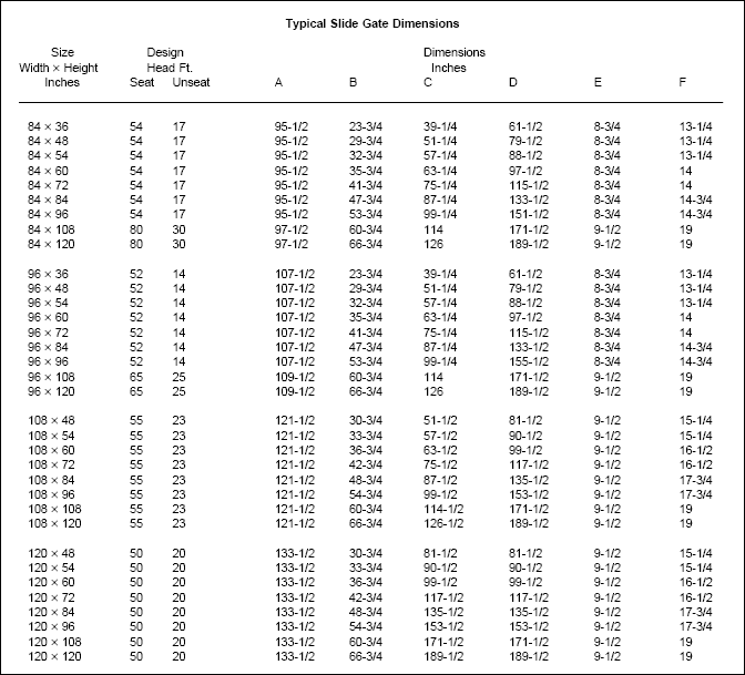
Figure D-3. Typical slide gate dimensions (Continued).


