Mechanical and Electrical Design of Pumping Stations - 29...
Chapter - 29 : Appendix E - Head Loss Methods and Formulas...
E-l. General...
This appendix shows the different methods and formulas
used to determine the head losses occurring in a pumping
station. For stations with complex discharge configurations
and which are over 2,000-cfs total capacity, consideration
should be given to performing a model test to
confirm the losses. This is particularly important when
the low head determines the size of the pump driver and
the losses are greater than 15 percent of the total head.
All losses should be determined for the maximum flow
rate expected to occur for that pumping condition.
E-2. Internal Pipe Losses...
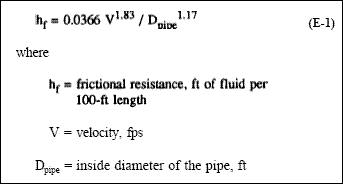
( a ) Friction losses.
The Darcy-Weisbach formula can
be used to determine friction losses in circular pipes.
This formula is preferable to other formulas since it takes
into consideration all the variable conditions. For water
temperatures above 60 O F. and using the friction factors
found in typical Corps of Engineers discharge pipe
systems, the following formula (in the form of Hazen
and Williams) applies :
( b ) Bend losses.
Bends are usually constructed either
by fabrication of mitered cut straight pieces welded
together or of cast or forged construction. Friction factor
“K” can usually be obtained from various charts and
tables. The inside diameter of the pipe in used to locate
the correct friction factor “K.” The loss for the bend is
found by multiplying the “K” value by the velocity head
occurring in that section of pipe.
( c ) Entrance, exit, and other losses.
Other losses
occur when a section of piping changes in diameter.
These changes in size can be from something less than
one pipe diameter to an infinitely greater diameter, such as a discharge into a pool or lake where the velocity
downstream of the pipe is zero. Various charts and
tables are available for determining the appropriate friction
factor “K” for the various fittings, increasers, and
reducers. Chart E-l shows the various water surfaces for
open discharges from vertical tubes such as used with
submersible pump installations. When using this chart,
the velocity head would not be added into the system
losses since this loss is expended in obtaining the height
of water above the vertical pipe exit. It is also seen from
the chart that the elevation of the water is also dependent
on the discharge bay dimensions.
E-3. External Losses...
( a ) General.
The capacity used to determine the
external head losses is usually calculated on the basis of
total station capacity. An exception to this would be the
loss through a single gate opening on an individual pump
sump.
( b ) Discharge chamber losses.
The head loss in a
discharge chamber usually is caused by a constriction in
area at its exit. This restriction is usually the stop log
slots used for dewatering the chamber for repair of a flap
gate during high discharge stages. A critical depth condition
(Figure E-l) can occur at this location if the water
level downstream of this point is at a lower elevation.
The discharge chamber critical depth is determined using
the formula shown on Chart E-2. This formula applies
* when a free discharge exists beyond the stop log slot at
the exit of the discharge chamber. In order to obtain
flow in the discharge chamber, a head of water is
required at the opposite end of the chamber. This head
of water is added to the water elevation caused by either
the critical depth condition at the stop log slots, or the
downstream water elevation, whichever is greater. The
head of water is equal to the velocity head occurring with
the depth of water at the stop log slots. An example of
calculation of the critical depth and the resulting
discharge chamber depth is shown below. It can be seen
that the real head on a pump may be greater because of
the artificial head created by the losses in the discharge
chamber. It is required to determine which is greatest,
the water level in the discharge chamber created by the
restriction or the center-line elevation of the flap gates.
The center-line elevation of the flap gate is used to determine
the low static head whenever it is higher than the
water level, in the discharge chamber, occurring for that
pumped flow rate. The slope of the water surface in the
chamber will be greatest at the opposite end from the
constriction, and usually not at the exact location of all the discharge flap gates. For purposes of head determination,
it is assumed that the greatest water level
occurring in the discharge chamber will be effective for
all the pump discharges.
( c ) Trashrack losses.
Head loss through the trashracks
should be less then 6 inches for a properly
designed rack that is raked regularly. A head loss value
of 6 inches will be used when determining the trashrack
portion of the total external losses. It is possible to
exceed this value when the rack becomes partially
clogged with debris; therefore the structure design of the rack should be in accordance with EM 1110-2-3104. In
unusual cases where the design of the rack is such that
for a clean rack the losses would be greater than
6 inches, the calculated loss plus a 6-inch margin should
be used for the head loss.
( d ) Gate opening losses.
The head loss through gate
openings is assumed to be equal to the velocity head that
occurs for the gate opening. If multiple gate openings
occur in the water path to the pumps, then a loss would
occur at each gate opening and be additive.
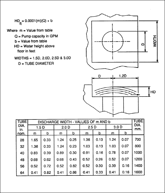
Chart E-1. Open tube losses.
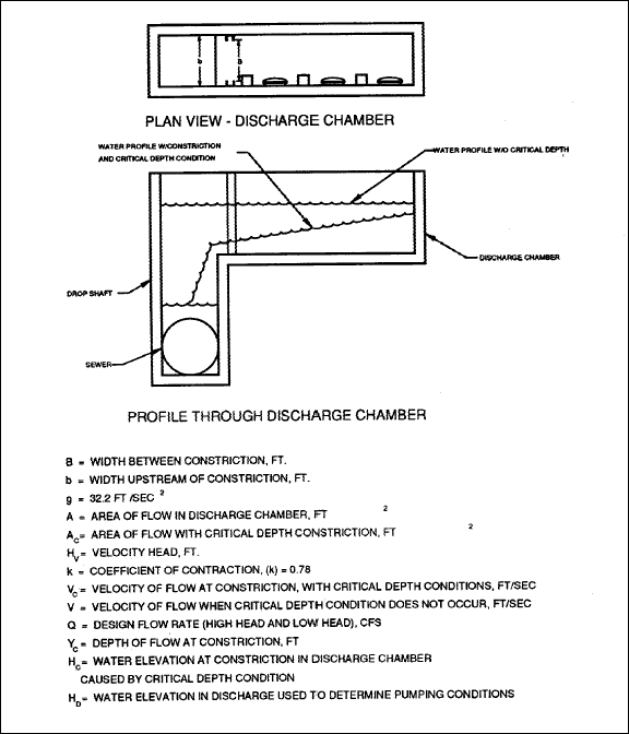
Figure E-1. Discharge chamber critical depth.
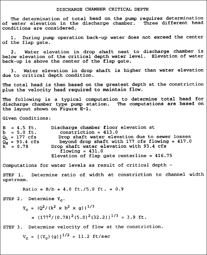
Chart E-2. Chart E-2. Critical depth condition (Sheet 1 of 3).
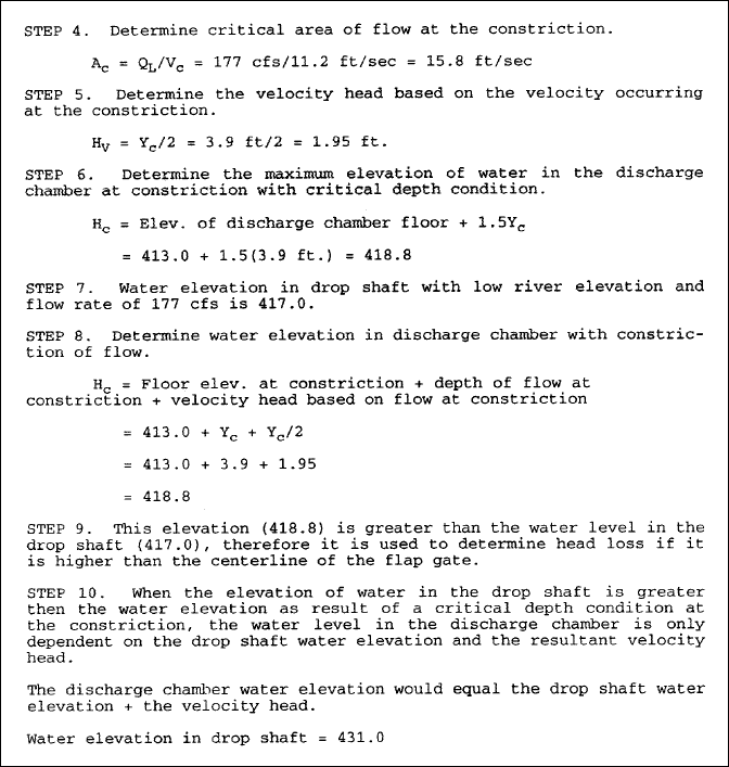
Chart E-2. Chart E-2. Critical depth condition (Sheet 2 of 3).
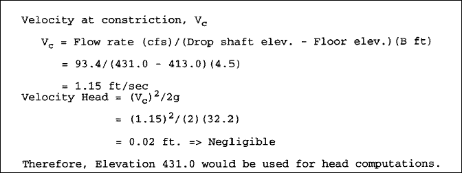
Chart E-2. Chart E-2. Critical depth condition (Sheet 3 of 3).


