Mechanical and Electrical Design of Pumping Stations - 33...
Chapter - 33 : Appendix I - Formed Suction Intake - Geometry Limitations...
I-1. Purpose...
This appendix provides guidance necessary to properly
select the best, most cost-effective formed suction intake
(FSI) design.
l-2. Background...
The U.S. Army Engineer Waterways Experiment Station
(WES) conducted research to determine by how much
the height of the FSI could be reduced without adversely
affecting its performance. ETL 1110-2-327 presents, in
detail, the results of the research. Results of prior
research conducted at WES about the basic FSI design
are presented in Technical Report HL-90-l. Formed
Suction Intake Approach Appurtenance Geometry
(Fletcher 1990). The 1990 report provided guidance for
the design of FSI external appurtenance geometry (pump
bay width and/or length) relative to the direction of
approaching flow, discharge, and submergence. The
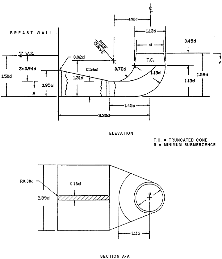
type 1 design (Figure I-l) provided the optimum design
at that time. The research presented here was initiated
by requests from field personnel involved in pumping
station design. The field wanted to know how to reduce
the height of the type 1 FSI. Reducing the height of the
FSI impacts favorably on the design of a pumping station.
It raises the sump floor and reduces the elevation
of the impeller. This in turn reduces excavation and increases the available static suction head on the pump
impeller.
l-3. Test Results and Recommendations...
Site-specific model tests conducted at WES demonstrated
that changing one or more of the FSI’s internal dimensions
adversely affected the flow distribution inside the
FSI. The minimum permissible height of an FSI was
determined by conducting tests to evaluate independently
and compositely the limiting values for the radius of the
roof curve, the cone height, and the height of the roof
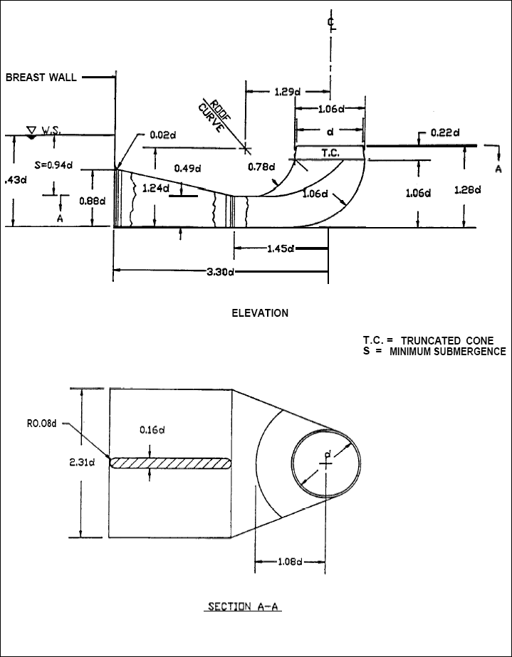
curve above the floor of the FSI. The type 10 FSI (Figure
I-2) represents the optimum design, i.e., a design
with the minimum permissible height. By reducing the
cone height from 0.45d to 0.22d and the height of, the
roof curve above the floor from 0.56d to 0.49d, the type
10 design changed the overall height of the type 1 design
from 1.58d to 1.28d. This provided a 19-percent reduction
in the overall height. Based on the test results, it is
recommended that the height of the FSI not be less than
1.28d and that the cone height and the height of the roof
curve above the floor not be less than 0.22d and 0.49d
respectively. The dimensions of the FSI are provided in
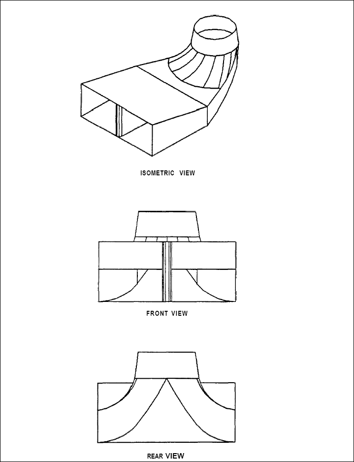
terms of the throat diameter d. Various views of the FSI
are shown in Figure 1-3. The isometric view shown in
Figure I-3 clarifies the isometric view shown in
ETL 1110-2-327. The ETL shows horizontal lines in the
roof portion of the FSI. These were intended to be a
drafting technique, not a method of construction. The
roof should be constructed in a manner similar to that
shown in Figure I-3.

Figure I-1. FSI type 1 design.

Figure l-2. FSI type 10 design.

Figure l-3. Typical FSI.


