Types of Sewers...

Domestic wastewater collection systems are generally composed of pipes buried underground at elevations that permit the collection of wastes by gravity. It is common practice to design on the basis that the pipes will be completely full when accommodating peak flows. For this reason, open - channel flow conditions prevail most of the time the pipes are in service. Although several empirical equations have been used in the selection of pipes for collection systems, the Manning equation has come into more general use for such purposes.

Types of Collection Systems...

Sanitary sewers : Often identified as separate sewers, sanitary sewers were developed to remove domestic wastes from residential areas. Originally, the flow in sanitary sewers was by gravity. More recently, both pressure and vacuum sewers have been used to serve areas where gravity sewers would be difficult and costly to install and maintain. Combined sewers : Domestic wastewater and stormwater are collected together in combined sewers. Although the use of combined sewers persist in many of the older cities in the world, they are seldom constructed today.


Types of Sewers...

Seperate systems are composed of several elements ; Building sewers : Building sewers, sometimes called "building connections", connect to the building plumbing and are used to convoy wastewater from the buildings to lateral or branch sewers, or any other sewer except another building sewer. These pipes generally have a diameter of 15 cm or more and are placed at grades no less than 1 or 2 %. Building sewers discharge into collector sewers (lateral or branch). Lateral or branch : Lateral sewers form the first element of a wastewater collection system and are usually in streets or special easements. They are used to collect wastewater from one or more building sewers and convey it to a main sewer. Main sewers : Main sewers are used to convey wastewater from one or more lateral sewers to trunk sewers or to intercepting sewers. Trunk sewers : Trunk sewers are large sewers that are used to convey wastewater from main sewers to treatment or other disposal facilities or to large intercepting sewers. Intercepting sewers : Intercepting sewers are larger sewers that are used to intercept a number of main or trunk sewers and convey the wastewater to treatment or other disposal facilities.

"Definition Sketch for Types of Sewers"...
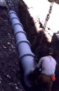
Sanitary Sewers...

Design Criteria...

· Design and install all sanitary sewer mains, side sewers (laterals), sewer lift stations, telemetering facilities, and sewer system appurtenances in accordance with WSDOT/APWA Standard Specifications and the Washington State Department of Ecology “Criteria for Sewage Works Design.”
· Provide engineering calculations used to size the piping.
· Bury mains with at least 36 inches of cover from finish grade to top of pipe. Use Seattle aggregate No. 9 for pipe bedding. Refer to the section on earthwork for backfill requirements.
· Generally use pipe that is 8 inches or larger in diameter. Sewer pipe 6 inches in diameter may be used if approved by University staff.
· Install sewer mains below water mains at crossings to provide a vertical separation of at least 18 inches between the invert of the water pipe and the crown of the sewer pipe.
· For gravity sewers, provide a manhole every 300 feet or less, and at changes in pipe direction or diameter.
· For pressure sewers, install clean-outs every 100 feet or less, and at changes in pipe directions.
· For sewer force mains, use only piping with restrained joints.
· Use 54-inch diameter manholes unless approved by University staff.
· Refer to Utility Corridor Arrangement drawing (see Roadways section) for piping placement under roadways.
· Install clean-outs at connections to buildings and ensure that an electrical receptacle is available within 100 feet.
· Avoid the use of lift stations. Where lift stations are necessary discuss with Engineering Services. Provide remote high level alarms, self-priming pumps, and auxiliary power with an automatic transfer switch.

Design Evaluation...

The following information is required to evaluate the design :

· Programming Phase: Statement of design intent.
· Schematic Phase: Drawings showing existing utilities and a narrative material and system description.
· Design Development Phase: Demolition plans, utility plans showing new and existing utilities, utility details, and an outline specification.
· Construction Document Phase: Complete plans and specifications and the following :
( 1 ) Pipe sizes, routing, points of connection, trench and bedding details, connection and joint details, manhole plans and sections, clean-out details, and building penetration details. ( 2 ) Plan(s) showing all existing underground tunnels and utilities (power, communications, gas, water, storm drain, sanitary sewer, and street lighting.) A survey drawing may be adequate for this purpose, providing it has been reviewed to ensure that all utilities are included and that each utility is clearly distinguishable from other drawing information. ( 3 ) Include drawing and specification notes to indicate that the Contractor shall notify the Utility Notification Center (1-800-424-5555) at least two full working days before digging. When contacting the Utility Location Center, the Contractor shall also contact the University Construction Coordinator and request the University to hire a professional utility locator to locate University utilities. ( 4 ) Invert elevations at the inlet and outlet of each manhole, at building connections, where sewer main crosses water distribution main, and at changes in grade, alignment, or pipe size. ( 5 ) Grate and cover elevations. ( 6 ) Pipe slopes. ( 7 ) For projects where the utility plans are an assembly of multiple sheets, provide a simplified composite utility plan showing all existing and new utilities on one sheet.

Construction Submittals...

· Provide standard industry submittal requirements.

Related Sections...

· Earthwork.
· Roadways.
· Mechanical - Waste & Drains.

Products, Materials and Equipment...

· All products, materials, and equipment shall conform to WSDOT/APWA Standards.
· Piping: SDR 35 PVC pipe per ASTM D3034 for sizes 12 inches in diameter and below, and reinforced concrete pipe per ASTM 67 for sizes above 12 inches in diameter. Exception : Use ductile iron pipe or a ductile iron sleeve where high surface loads exist, under roadways, and where minimum cover cannot be achieved.
· Pipe connections: Use fittings made of the same material as the connecting pipe. Use an appropriate adapter when changing materials (e.g. when penetrating a concrete manhole with a PVC pipe.)
· Exterior below grade pipe penetrations: Link-Seals, or approved substitution.
· Manhole lids: Ductile iron, permanently marked “SEWER”. Do not use locking lids.

Installation, Fabrication and Construction...

· Install, clean, and test sewers in accordance with WSDOT/APWA Standard Specifications.
· The Construction Coordinator shall make test arrangements with the Contractor and shall notify University Engineering Staff as to the date and time of testing. University staff must witness and approve all testing before the sewer may be placed in service.
· Refer to the following University drawings : ( 1 ) Acid Waste Manhole, ( 2 ) 54” or Larger Drop Manhole Interior (see Storm Drainage section), ( 3 ) Site Work & Utilities Symbols (see Storm Drainage section), ( 4 ) Roadway & Utility Corridor Arrangement (see Roadways section).
· Refer to the following City of Seattle (COS) Standard Plans : ( 1 ) Manhole (COS 201.1a), ( 2 ) Drop Connection (COS 233.1), ( 3 ) 8” Clean-out (COS 280), ( 4 ) Typical Trench Section (COS 284), ( 5 ) Pipe Bedding (COS 285.1).

Construction of the Sewer System...


"Sanitary Sewer"...

Manholes...

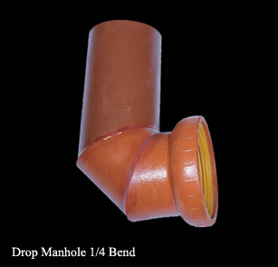
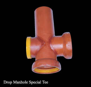
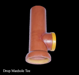
"Standard Outside Drop Manhole"...

"Standard Inside Drop Manhole"...

Acid Waste Manhole...

"Acid waste manhole"...

"Detailed info and drawings about the manholes - 1"...

"Detailed info and drawings about the manholes - 2"...

Manholes are used to interconnect two or more sewers and to provide entry for sewer cleaning. For sewers that are 1,200 mm and smaller, manholes should be located at changes in size, slope, or direction. Sometimes the slope of collector pipes coming into a manhole from streets other than the one under consideration will govern the elevation of the bottom of a manhole. Unless the manhole is specifically designed as a drop manhole, the inverts of all pipes coming into a manhole should be located at the elevation of the bottom of the manhole.

"Sanitary Sewer Drop Manhole"...

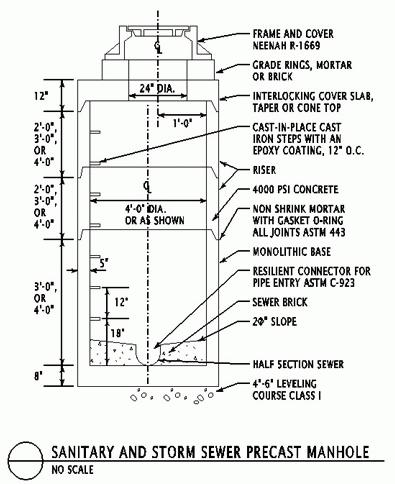
"Sanitary and Storm Sewer Precast Manhole"...
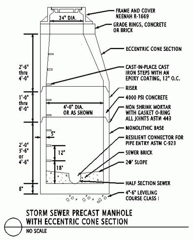
"Storm Sewer Precast Manhole"...

The following should be covered in the design guidelines for manholes ; (1) All manholes should be constructed with a drop to self - cleanse. The minimum drop for an outlet at right angles to an inlet of the same diameter should be 5 cm. (2) All manholes in drainage, gutter, or similar low - lying points outside the crown of the street should be fitted with water - tight gasketed covers, (3) All manholes on easement outside travelled rights - of - way such as sidewalks, side - lot, and back - lot areas should be fitted with tamper - proof locking lids. Locking manholes on easement in parking lots or along public roadways could be waived at the city's discretion, (4) Connections to existing manholes where no stubout is available should be made with a core drill or concrete saw, never with a jack - hammer. The new invert elevation should conform with 25 cm depth, and a minimum of 5 cm above the existing manhole outlet. It will help avoid delays and disputes to add a note by each manhole tap in the plans with words to the effect of "tap existing manhole by core - drilling or sawing". Install approved commercial boot adapter with latex concrete bonding agent and non - shrink grout per specs. Rechannel manhole base per standard drawing, (5) Wherever manholes are to be constructed over existing sewers, the existing pipe material and diameter should be determined in the field and shown on the plans, (6) Building drains (service laterals) should be connected to wyes or tees, instead of manholes. At the city's discretion, house connections to new pre - cast manhole bases could be allowed using the specified manhole adapters and casting self - cleansing channels in the pre - cast base. If allowed, house connections per manhole should not exceed 2, (7) Preliminary rim elevations for manholes should be shown. Manholes under 15 cm deep from invert to rim should be flattop to facilitate access for inspection and maintenance, (8) Installing toning wire into manholes is discouraged because the holes through each manhole are too often a source of groundwater leakage. Sewer pipe installations between manholes normally do not require toning wire to locate the sewer or services. Where necessary, commercial metallic tracer tape could be used, (9) The manholes on the project should be numbered on both plan and profile, using a consistent system of designation and (10) Whether to use or exclude alternative manhole materials such as plastic is the prerogative of the city or district responsible for maintenance of the system, and of the engineer stamping the plans.

Many cities allow manhole testing after the first lift of asphalt - cement, instead of requiring total completion of all the paving. Sometimes postponing manhole tests until paving may be unreasonable, as when bad weather prevents paving for an extended period. Some cities will now test for acceptance prior to paving if the contractor will first anchor the manhole neck and casting with a substantial concrete collar. Collars 12" thick by 6' to 8' square or 6' to 8' diameter have been used.