|
Oracle® Application Server Web Cache Administrator's Guide
10g Release 2 (10.1.2) B14046-04 |
|
 Previous |
 Next |
|
Oracle® Application Server Web Cache Administrator's Guide
10g Release 2 (10.1.2) B14046-04 |
|
 Previous |
 Next |
The Oracle Application Server Concepts and Oracle Application Server Installation Guide provide an overview of the recommended topologies for Oracle Application Server. This chapter presents several detailed scenarios for deploying OracleAS Web Cache.
|
Note: The topologies described in this chapter depict OracleAS Web Cache on a dedicated computer. However, you can deploy OracleAS Web Cache on the same computer as the Oracle Application Server. |
This chapter contains these topics:
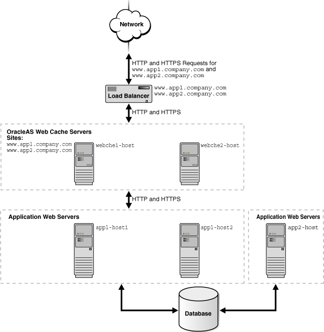
Figure 5-1 shows OracleAS Web Cache in a common Oracle Application Server configuration. A tier of OracleAS Web Cache servers cache content for a tier of application Web servers. The application Web servers app1-host1 and app1-host2 provide content for site www.app1.company.com, and app2-host provides content for www.app2.company.com. The two OracleAS Web Cache servers reside on dedicated, fast one or two-CPU computers. To increase the availability and capacity of a Web site, these servers are configured as either a cache cluster or a failover pair.
Oracle recommends a hardware load balancer to ping each OracleAS Web Cache server on a periodic basis to check the status of the cache. You should configure the load balancer with the same ping URL you configure for the auto-restart mechanism, as described in"Task 3: Configure Auto-Restart Settings".
As a cache cluster, the two OracleAS Web Cache servers provide failure detection and failover. If an OracleAS Web Cache server fails, other members of the cache cluster detect the failure and take over ownership of the cached content of the failed cluster member and masks any cache failure. OracleAS Web Cache maintains a virtual single cache of content despite a cache failure. The load balancer distributes the incoming requests among cache cluster members. The cache cluster members process the incoming requests. For requests that are not stored in the cache, OracleAS Web Cache distributes the requests to an application Web server respective to the site.
As a failover pair, both OracleAS Web Cache servers are configured to cache the same content. When both OracleAS Web Cache servers are running, a load balancer distributes the load among both servers. If one server fails, the other server receives and processes all incoming requests.
Figure 5-1 Deploying OracleAS Web Cache In a Common Configuration
To configure this topology:
Register the IP address of the load balancer with www.app1.company.com and www.app2.company.com.
Configure the load balancer with OracleAS Web Cache server host names webche1-host and webche2-host and configure it to ping each cache server periodically to check the status of the cache.
If configuring a cache cluster, specify webche1-host and webche2-host as cluster members.
Configure the OracleAS Web Cache servers with the following:
Receive HTTP and HTTPS requests on designated listening ports
Send HTTP and HTTPS requests to application Web servers app1-host1, app1-host2, and app2-host on designated listening ports
Virtual host site definition for www.app1.company.com mapped to app1-host1 and app1-host2
Virtual site definition for www.app2.company.com mapped to app2-host
|
See Also:
|
This section describes the following specialized topologies:
Many Web sites have several data centers. For networks with a distributed topology, you can deploy OracleAS Web Cache at each of the data centers in a distributed cache hierarchy. Figure 5-2 shows a distributed topology in which OracleAS Web Cache servers are distributed in offices in the United States and Japan. The application Web servers are located in the United States office, centralizing the data source to one geographic location. The central caches in the United States cache content for application Web servers app1-host1, app2-host2, and app2-host, and the remote cache in Japan caches content from the central caches.
Clients make requests to local DNS servers to resolve www.app1.company.com and www.app2.company.com. The local DNS servers are routed to the authoritative DNS server for the respective sites. The authoritative DNS server uses the IP address of the client to pick the closest OracleAS Web Cache server to satisfy the request. Then, it returns the IP address of the appropriate OracleAS Web Cache server to the client.
Figure 5-2 Deploying an OracleAS Web Cache Hierarchy

To configure this topology:
Register the IP address of the load balancer with www.app1.company.com and www.app2.company.com.
Configure the load balancer with OracleAS Web Cache server host names us.webche1-host and us.webche2-host and configure it to ping each cache server periodically to check the status of the cache.
Configure OracleAS Web Cache servers us.webche1-host and us.webche1-host with the following:
Receive HTTP and HTTPS requests on designated listening ports
Send HTTP and HTTPS requests to application Web servers app1-host1, app1-host2, and app2-host on designated listening ports
Virtual host site definition for www.app1.company.com mapped to app1-host1 and app1-host2
Virtual site definition for www.app2.company.com mapped to app2-host
Configure OracleAS Web Cache server jp.webche-host with the following:
Receive HTTP and HTTPS requests on designated listening ports
Send HTTP and HTTPS requests to application Web servers us.webche1-host and us.webche2-host on designated listening ports
Virtual host site definition for www.app1.company.com mapped to app1-host1 and app1-host2
Virtual site definition for www.app2.company.com mapped to app2-host
|
See Also:
|
You can make OracleAS Web Cache highly available without a hardware load balancer by configuring:
OracleAS Web Cache solely as a software load balancer or reverse proxy
With this option, you configure OracleAS Web Cache solely for providing load balancing or reverse proxy support. Specifically, you replace the hardware load balancer with one or more caches.
Operating system load balancing capabilities
With this option, you configure the operating system to load-balance incoming requests across multiple caches. You configure multiple caches as nodes of the same cluster. Incoming requests are distributed among the caches. When the operating system detects a failure of one of the caches is detected, automatic IP takeover is used to distribute the load to the remaining caches in the cluster configuration. This feature is supported on many operating systems, including Linux, Windows 2000 Advanced Server, Windows 2000 Datacenter Server, and Windows 2003 (all editions).
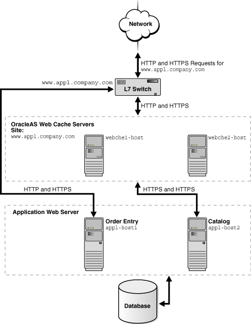
Many Web sites contain cacheable public content and non-cacheable, transactional or protected content. For these Web sites, you can use OracleAS Web Cache servers to cache content for only the portions of the Web site with the cacheable content.
Figure 5-3 shows a Layer 7 (L7) switch passing catalog requests to OracleAS Web Cache servers webche1-host and webche2-host and order entry requests to application Web server app1-host1. An L7 switch operates at Layer 7, the Application Layer layer, of the Open Systems Interconnection (OSI) model. L7 switches determine where to send requests based on URL content.
Figure 5-3 Accelerating Portions of a Web Site with an Layer 7 Switch
To configure this topology:
Register the IP address of the L7 switch with www.app1.company.com.
Configure the L7 switch with OracleAS Web Cache server host names webche1-host and webche2-host.
Configure the OracleAS Web Cache servers with the following:
Receive HTTP and HTTPS requests on designated listening ports
Send HTTP and HTTPS requests to application Web servers app1-host1 and app1-host2 on designated listening ports
Virtual host site definition for www.app1.company.com mapped to app1-host1 and app1-host2
|
See Also:
|
This section describes the following topologies:
With OracleAS Web Cache deployed inside or outside a firewall. "Deploying OracleAS Web Cache with Firewalls" describes this scenario.
With OracleAS Web Cache listening for incoming requests on two ports, one for HTTPS requests and one for HTTP requests. You can configure a load balancer to pass requests to the appropriate listening port. In addition, you can configure OracleAS Web Cache with SSL acceleration hardware to off-load the SSL operations. "Deploying OracleAS Web Cache with SSL Acceleration Hardware" describes this scenario.
With one OracleAS Web Cache server listening for HTTP requests and another OracleAS Web Cache server listening for HTTPS requests. You can configure a load balancer to pass requests to the appropriate OracleAS Web Cache server. "Routing HTTPS Requests to a Dedicated Cache" describes this scenario.
With OracleAS Web Cache listening only for HTTP requests. All HTTPS requests are routed to the application Web server. You can configure a load balancer to pass HTTPS requests directly to the application Web server. "Routing HTTPS Requests Around OracleAS Web Cache" describes this scenario.
With OracleAS Web Cache caching content for Oracle HTTP Servers running Oracle Application Server Single Sign-On partner applications and load balancing the redirected requests from the partner applications to the Single Sign-On servers. "Routing Single Sign-On Server Requests" describes these scenarios.
You can deploy OracleAS Web Cache inside or outside a firewall. Deploying OracleAS Web Cache inside a firewall ensures that HTTP traffic enters the Demilitarized Zone (DMZ), but only authorized traffic from the application Web servers can directly interact with the database. When deploying OracleAS Web Cache outside a firewall, the throughput burden is placed on OracleAS Web Cache rather than the firewall. The firewall receives only requests that must go to the application Web servers. This topology requires securing OracleAS Web Cache from intruders.
Security experts disagree about whether caches should be placed outside the DMZ. Oracle recommends that you check your company's policy before deploying OracleAS Web Cache outside the DMZ.
You can configure OracleAS Web Cache to receive both HTTP and HTTPS requests. You can off-load some of the strain of SSL operations on the OracleAS Web Cache CPUs by using SSL acceleration hardware.
Figure 5-4 shows OracleAS Web Cache servers webche1-host and webche2-host deployed with SSL acceleration hardware. Both servers receive HTTP and HTTP requests, with the HTTPS requests being processed by the SSL acceleration hardware. Both OracleAS Web Cache servers send origin server requests to app1-host1 and app1-host2.
|
Note: Oracle Application Server supports nCipher's BHAPI-compliant hardware for deployment on OracleAS Web Cache servers. Seehttp://www.ncipher.com for more information about nCipher.
|
Figure 5-4 Routing HTTPS Requests to SSL Acceleration Hardware

To configure this topology:
Ensure that the load balancer supports sticky sessions so that HTTPS requests for a given user session are bound to the same OracleAS Web Cache server.
Register the IP address of the load balancer with www.app1.company.com.
Configure the load balancer with OracleAS Web Cache server host names webche1-host and webche2-host. Configure the load balancer to send HTTP and HTTPS requests to webche1-host and webche2-host and to ping each cache server periodically to check the status of the cache.
Configure the OracleAS Web Cache servers with the following:
Receive HTTP and HTTPS requests on designated listening ports.
Send HTTP and HTTPS requests to application Web servers app1-host1 and app1-host2 on designated listening ports.
Virtual host site definition for www.app1.company.com, with HTTP and HTTPS ports, mapped to app1-host1 and app1-host2.
If using client-side certificates, require client-side certificates for the HTTPS listening ports. In addition, for a cache cluster, allow cluster members to pass certificate information in headers to other cluster members and disallow acceptance of such headers from all other entities.
|
Note: In a cache cluster, you must disallow acceptance of headers containing client-side certificate information to prevent receipt of certificate information in a header from any entity other than a peer cluster member. See "Task 7: (Optional) Require Client-Side Certificates" for more information. |
|
See Also:
|
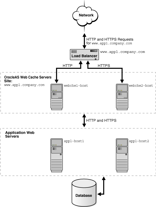
You can configure one OracleAS Web Cache server to listen for HTTP requests and another OracleAS Web Cache server to listen for HTTPS requests.
Figure 5-5 shows two OracleAS Web Cache servers receiving requests. HTTP requests are served from server webche1-host and HTTPS requests are served from server webche2-host. Both OracleAS Web Cache servers send origin server requests to app1-host1 and app1-host2.
Figure 5-5 Routing HTTPS Requests To a Dedicated OracleAS Web Cache Server
To configure this topology:
Register the IP address of the load balancer with www.app1.company.com.
Configure the load balancer with OracleAS Web Cache server host names webche1-host and webche2-host. Configure the load balancer to send HTTP requests to webche1-host and HTTPS requests to webche2-host and to ping each cache server periodically to check the status of the cache.
Configure OracleAS Web Cache server webche1-host with the following:
Receive HTTP requests on a designated HTTP listening port
Send HTTP requests to application Web servers app1-host1 and app1-host2 on designated HTTP listening ports
Virtual host site definition for www.app1.company.com, with an HTTP port, mapped to app1-host1 and app1-host2
Configure OracleAS Web Cache server webche2-host with the following:
Receive HTTPS requests on a designated HTTPS listening port.
Send HTTP requests to application Web servers app1-host1 and app1-host2 on designated HTTP listening ports.
Virtual host site definition for www.app1.company.com, with an HTTPS port, mapped to app1-host1 and app1-host2.
If using client-side certificates, require client-side certificates for the HTTPS listening ports. In addition, for a cache cluster, allow cluster members to pass certificate information in headers to other cluster members and disallow acceptance of such headers from all other entities.
|
Note: In a cache cluster, you must disallow acceptance of headers containing client-side certificate information to prevent receipt of certificate information in a header from any entity other than a peer cluster member. See "Task 7: (Optional) Require Client-Side Certificates" for more information. |
|
See Also:
|
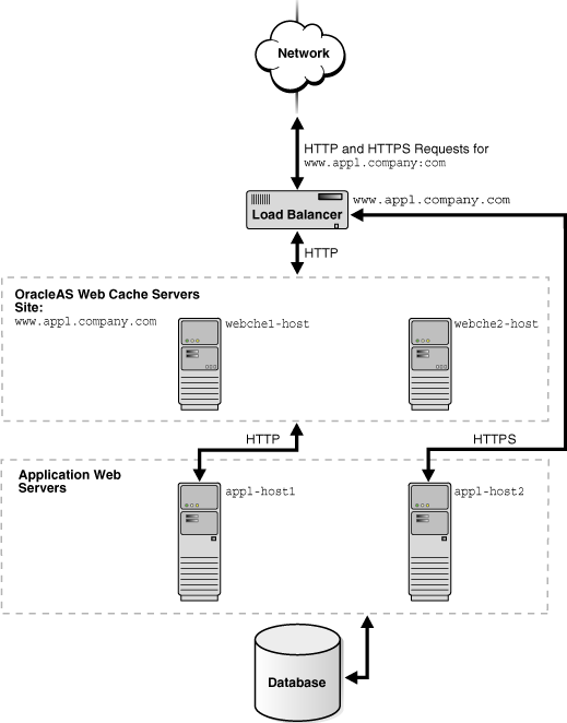
For many applications, HTTPS is required for secure transactions that should not be cached. For example, checkout pages on an e-commerce site that require credit card information should not be cached. For this type of Web site, you can use a load balancer to pass all HTTP requests to OracleAS Web Cache, and pass all HTTPS requests for secure pages directly to a particular application Web server.
Figure 5-6 shows a load balancer passing HTTP requests to OracleAS Web Cache server webche1-host and webche2-host and HTTPS requests to application Web server app1-host2. Note that HTTPS requests could also be passed to app1-host1.
Figure 5-6 Routing HTTPS Requests To an Application Web Server
To configure this topology:
Register the IP address of the load balancer with www.app1.company.com.
Configure the load balancer with OracleAS Web Cache server host names webche1-host and webche1-host and application Web server host name app1-host2.
Configure the OracleAS Web Cache servers with the following:
Receive HTTP requests on a designated HTTP listening port
Send HTTP requests to application Web servers app1-host1 on an HTTP listening port
Virtual host site definition for www.app1.company.com, with an HTTP port, mapped to app1-host1
|
See Also:
|
Because login and logout requests to Single Sign-On servers are both secure and time sensitive, you cannot cache content from the Single Sign-On servers. You can configure OracleAS Web Cache as a software load balancer in front of multiple Single Sign-On mid-tiers, similar to a hardware-based load balancer approach. You can also configure OracleAS Web Cache to cache content for Oracle HTTP Servers running Oracle Application Server Single Sign-On partner applications. By default, mod_osso protected pages are marked as non-cacheable to ensure that requests for these pages are redirected through Oracle Application Server Single Sign-On servers.
Figure 5-7 shows OracleAS Web Cache caching content for the Oracle HTTP Servers app1-host and app1-host2 and a load balancer routing the requests from the partner applications to the Single Sign-On servers sso-host1 and sso-host2. No content from the Single Sign-On servers is cached. This topology requires that the Oracle HTTP Servers be clustered so that OracleAS Web Cache can send requests to either partner application.
Figure 5-7 Routing Single Sign-On Server Requests to the Single Sign-On Mid-Tier Around OracleAS Web Cache
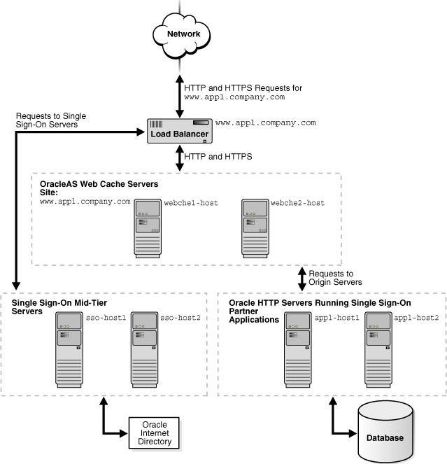
To configure this topology:
Ensure that the load balancer supports sticky sessions so that HTTPS requests for a given user session are bound to the same OracleAS Web Cache server.
Register the IP address of the load balancer with www.app1.company.com.
Configure the load balancer with OracleAS Web Cache server host names webche1-host and webche2-host. Configure the load balancer to send HTTP and HTTPS requests to webche1-host and webche2-host.
Configure the OracleAS Web Cache servers with the following:
Receive HTTP and HTTPS requests on designated listening ports.
Stateless load balancing of HTTP and HTTPS requests to clustered Oracle HTTP Servers app1-host1 and app1-host2 on designated listening ports.
Virtual host site definition for www.app1.company.com, with HTTP and HTTPS ports, mapped to app1-host1 and app1-host2.
If using client-side certificates, require client-side certificates for the HTTPS listening ports. In addition, for a cache cluster, allow cluster members to pass certificate information in headers to other cluster members and disallow acceptance of such headers from all other entities.
|
Note: In a cache cluster, you must disallow acceptance of headers containing client-side certificate information to prevent receipt of certificate information in a header from any entity other than a peer cluster member. See "Task 4: Configure HTTPS Port and Wallet Location for the Origin Server" for more information. |
|
See Also:
|