|
Oracle® Application Server Adapter for PeopleSoft User's Guide
10g Release 2 (10.1.2) B14060-02 |
|
 Previous |
 Next |
|
Oracle® Application Server Adapter for PeopleSoft User's Guide
10g Release 2 (10.1.2) B14060-02 |
|
 Previous |
 Next |
This chapter contains the following examples:
The event and service scenarios shown depend on the following prerequisites and configuration steps:
Prerequisites
OracleAS Adapter for PeopleSoft installed on the Oracle Application Server.
OracleAS Database adapter deployed and configured.
Oracle BPEL PM Server properly configured and running.
Oracle JDeveloper properly installed.
|
See Also: Oracle Application Server Adapter Installation Guide |
Configuration Steps
The examples present all the configuration steps necessary for demonstrating service and event integration with PeopleSoft. The following cross references are given to identify where more information can be obtained.
Create a J2CA configuration, as BPEL PM is only compatible with the J2CA Connector. See "Creating a Configuration for J2CA" for more information.
Configure OracleAS Adapter for PeopleSoft for services and events. See Chapter 2, "Configuring OracleAS Adapter for PeopleSoft" for more information.
This topic illustrates PeopleSoft event integration. The demonstrated procedures describe design time and runtime.
Creating a Channel
You must create a separate channel for every inbound J2CA service and select that channel when you generate WSDL for inbound interaction using Application Explorer.
|
Note: If more than one inbound service share the same channel, event messages will not be delivered to the right BPEL process. |
To create a channel:
Click the Events node.
Expand the PeopleSoft node.
The ports and channels nodes appear in the left pane.

Right-click Channels and select Add Channel.
The Add Channel dialog box is displayed.
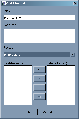
Provide the following information:
Enter a name for the channel, for example, PSFT_Channel.
Enter a brief description (optional).
From the Protocol list, select HTTP Listener.
Click Next.
When the Basic dialog box is displayed, enter the system information as specified in the following table:
| Parameter | Description |
|---|---|
| Port | Port on which to listen for PeopleSoft event data. |
| Server port | Port on which the host database is listening. |
| Synchronization Type | Choose from three synchronization options:REQUESTREQUEST_RESPONSEREQUEST_ACK |
Click OK.
The channel appears under the channels node in the left pane. An X over the icon indicates that the channel is currently disconnected.
Creating an Event
After you create a channel and verify that it is not started, you must create an event using Application Explorer.
To establish a connection to the PeopleSoft system and locate LOCATION:
Start Application Explorer.
Expand PeopleSoft.
Click a target name under the PeopleSoft node, for example, PSFTtarget.
Verify your connection parameters and provide the required password.
Right-click the target name and select Connect.
The x icon disappears, indicating that the target is connected.

Expand Messages and select LOCATION_SYNC.VERSION_1.
Right-click LOCATION_SYNC.VERSION_1.

Select Create Inbound JCA Service (Event).
The Export WSDL dialog box is displayed.
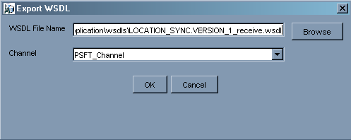
Description of the illustration bpel_39.gif
Perform the following steps:
In the WSDL File Name field, specify a name and location of the WSDL file.
In the Channel field, select the channel you created for this inbound service.
|
Note: You must create a separate channel for every inbound service. Verify that the channel is stopped before runtime. |
Creating a BPEL PM Server Connection
Before you design an inbound BPEL process, you must create a connection to your BPEL Server using JDeveloper. To create a server connection:
Open JDeveloper.
To display the connections, click the Connections tab at the bottom of the upper left pane in JDeveloper.
The following menu is displayed.
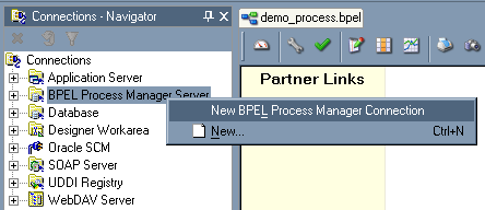
Right-click BPEL Process Manager Server and select New BPEL Process Manager Connection.
The Create BPEL Process Manager Connection - Welcome dialog box is displayed.
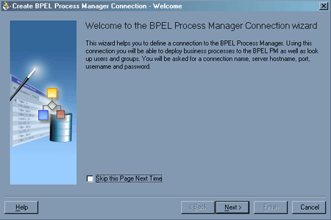
Click Next.
The Create BPEL Process Manager Connection dialog box is displayed.
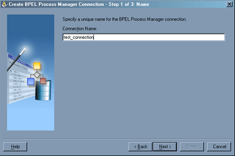
Specify a unique name for your BPEL Server connection and click Next.
Specify a valid host name and port number for the BPEL PM Server you wish to connect to.
Click Finish.
Your newly created server connection is displayed in the Connections tab under the BPEL Process Manager Server node.
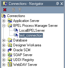
Designing the BPEL Process for the LOCATION_SYNC.VERSION_1 Inbound Service
To design a BPEL process for inbound interaction:
Click the Applications tab and select a workspace for your project.
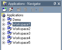
Right-click the workspace and select New Project.
The New Gallery dialog box is displayed.
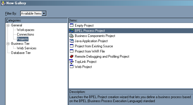
From the Items list, select BPEL Process Project and click OK.
The BPEL Process Project dialog box is displayed.
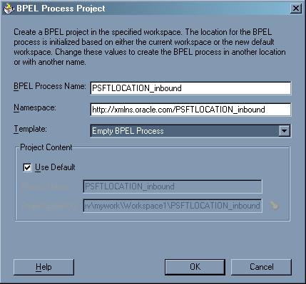
Perform the following steps:
Specify a name for the process, for example, PSFTLOCATION_inbound.
The Namespace field is updated automatically.
From the Template drop-down list, select Empty BPEL Process.
Click OK.
From the Process Activities pane on the right, drag and drop a PartnerLink to the visual editor.
The Create Partner Link dialog box is displayed.
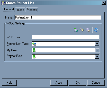
Click the WSIL browser icon (second icon from the left the WSDL File field).
The WSDL Chooser dialog box is displayed.

Expand your BPEL Server connection, then expand adapters, and then applications.
The WSDL Chooser dialog box is displayed.
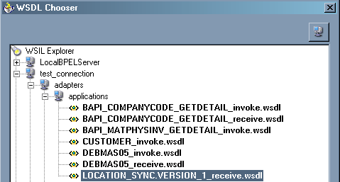
Select LOCATION_SYNC.VERSION_1_receive.wsdl and click OK.
The Create Partner Link dialog box is displayed.
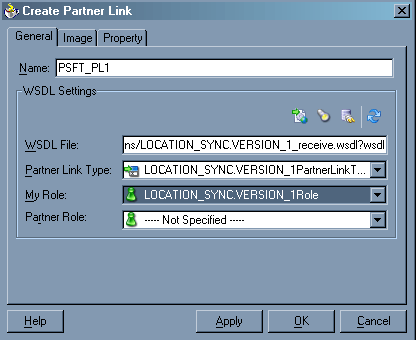
The WSDL File field displays the name and location of the selected WSDL file. The Partner Link Type field specifies the PartnerLink defined in the WSDL file.
Perform the following steps:
From the My Role drop-down list, select the default value LOCATION_SYNC.VERSION_1Role.
Leave the Partner Role field unspecified.
Click Apply, and then OK.
The new PSFT_PL1 PartnerLink appears in the visual editor.
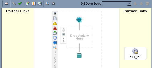
From the Process Activities pane on the right, drag a Receive activity to the visual editor and place it in the designated placeholder labeled Drop Activity Here.
Connect the Receive activity to the PSFT_PL1 PartnerLink.
The Edit Receive dialog box is displayed.
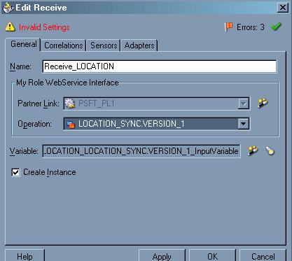
Perform the following steps:
Specify a name for the Receive Activity, for example, Receive_LOCATION.
Click the first icon to the right of the Variable field, then click OK in the Create Variable dialog box that is displayed.
Verify that the Create Instance check box is selected.
Click Apply.
The Receive dialog box should no longer display any warnings or errors.
Click OK.
Select Save from the File menu.
Deploying the BPEL Process for the LOCATION_SYNC.VERSION_1 Inbound Service
Triggering an Event in PeopleSoft to Test Event Runtime Integration
The following topic describes how to trigger an event in PeopleSoft to verify event integration using OracleAS Adapter for PeopleSoft.
To trigger an event in PeopleSoft:
Log in to PeopleSoft, select PeopleTools, Integration Broker, and then Node Definitions.
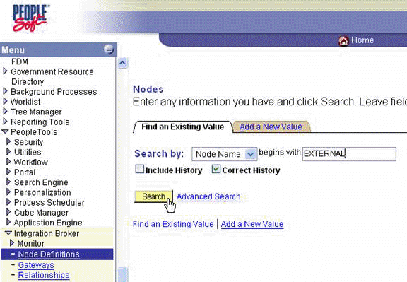
Enter the node name you will be using, for example, EXTERNAL; then click Search.
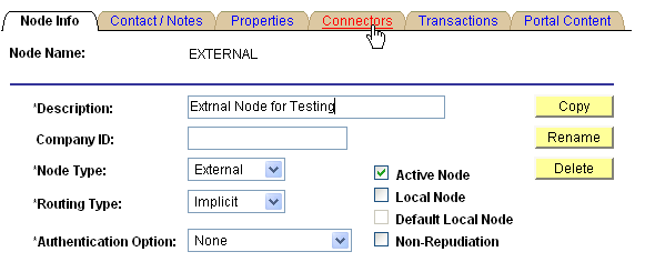
Click the Connectors tab.
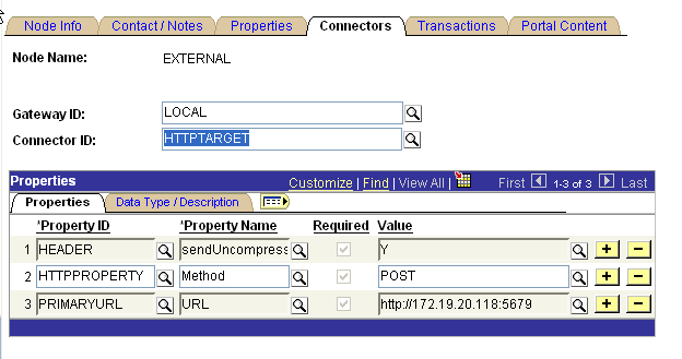
Enter HTTPTARGET in the Connector ID field; then enter the listener URL and its port in the PRIMARYURL field.
To save the configuration, click Save.
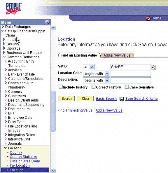
From Menu in the left pane, select Set Up Financials/Supply Chain, Common Definitions, Location, and then Location.
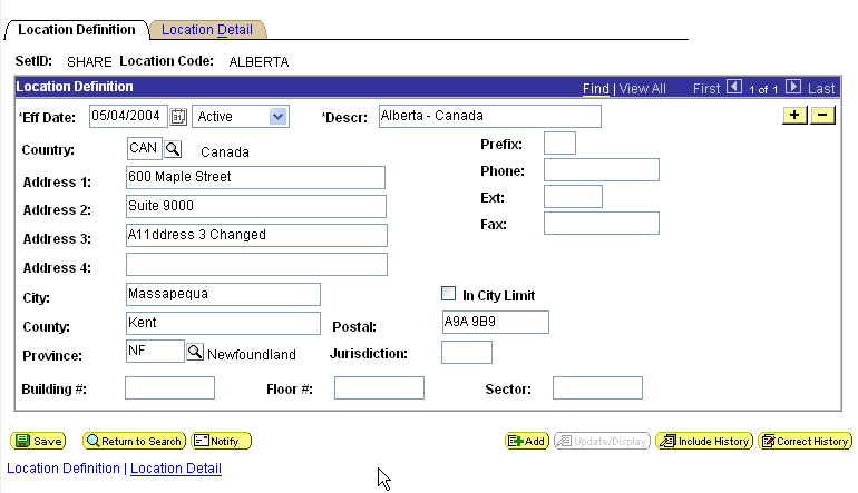
To find the location record you want to update, click Search; then make the changes and click Save.
When the change is saved, it triggers an event and sends the event to the listener.
Verifying the Results
To verify your results:
Log in to Oracle BPEL Console at
http://host:port/BPELConsole
Enter the password for your BPEL domain.
The default password is bpel.
Click the Instances tab.
Recently received runtime events are displayed in the Instances tab.

Click an instance, then click Audit to see the received event message.
This topic illustrates PeopleSoft service integration. The procedures describe design time and runtime.
Creating a Request-Response J2CA Service in Application Explorer
Before you design a process for PeopleSoft service integration, you must generate its respective WSDL file using Application Explorer.
To generate WSDL in Application Explorer:
Start Application Explorer and connect to a defined PeopleSoft target or create a new target.
See Connecting to PeopleSoft for more information.
Expand the PeopleSoft target to which you are connected.
Expand Component Interfaces > LOCATION.
Right-click LOCATION.
The following menu is displayed:

Click Create Outbound JCA Service (Request/Response).
The Export WSDL dialog box is displayed.

Click OK.
You are ready to design a BPEL process in JDeveloper.
Creating a BPEL PM Server Connection
Before you design an outbound BPEL process, you must create a connection to your BPEL Server using JDeveloper. See Creating a BPEL PM Server Connection for details on how to create the connection.
Creating a BPEL Project for a Synchronous BPEL Process
To create a BPEL Project for a synchronous BPEL process:
At the bottom of the upper left pane, click the Applications tab and select a workspace for your project.

Right-click the workspace and select New Project.
The New Gallery window is displayed.

From the Items list, select BPEL Process Project and click OK.
The BPEL Process Project dialog box is displayed.
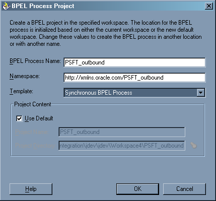
Perform the following steps:
Specify a name for the BPEL process.
The Namespace field is updated automatically.
From the Template drop-down list, select Synchronous BPEL Process.
Click OK.
Designing the BPEL Process for the LOCATION Outbound Service
From the Process Activities pane on the right, drag and drop a PartnerLink to the visual editor.
The Create Partner Link dialog box is displayed.

Click the WSIL browser icon (second icon from the left the WSDL File field).
The WSDL Chooser dialog box is displayed.

Expand your new server connection, then expand adapters, and then applications.

Select LOCATION_invoke.wsdl and click OK.
The WSDL File field in the Create Partner Link dialog box displays the name and location of the selected WSDL file. The Partner Link Type field specifies the PartnerLink defined in the WSDL file.
Perform the following steps:
Leave the My Role field unspecified. The role of the PartnerLink is null, as it will be synchronously invoked from the BPEL process.
From the Partner Role drop-down list, select the default value LOCATIONRole. This is the role of the BPEL process.
Click OK.
Select Save from the File menu.
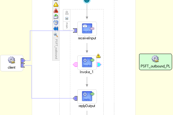
From the Process Activities pane on the right, drag an Invoke activity to the visual editor and place it between the Receive activity (receiveInput) and the Reply activity (replyOutput).
The Invoke process activity is shown in the following diagram view.
Drag the blue arrow from Invoke_1 and connect it to the PeopleSoft PartnerLink.
The Edit Invoke dialog box is displayed.
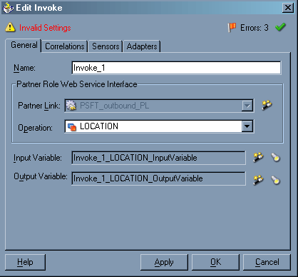
Perform the following steps:
Click the first icon to the right of the Input Variable field, then click OK in the Create Variable window that is displayed.
Repeat the previous step to create a default variable for Output Variable.
Click OK.
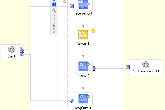
Drag an Assign process activity and drop it between receiveInput and Invoke_1.
The following image shows the new Assign activity in JDeveloper visual editor.
Double-click the Assign activity icon.
The Assign dialog box is displayed.
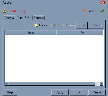
In the Copy Rules tab, click Create.
The Create Copy Rule dialog box is displayed.
Perform the following steps:
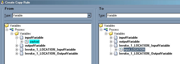
In the From pane, expand Variables, then inputVariable, and then highlight payload.
In the To pane, expand Variables, then Invoke_1_LOCATION_InputVariable, and then highlight input_LOCATION.
Your Create Copy Rule dialog box should look as follows:
To close the Create Copy Rule dialog box and the Assign dialog box, click OK.
From the Process Activities pane on the right, drag another Assign activity to the visual editor and place it between the Invoke activity (Invoke_1) and the Reply activity (replyOutput).
Double-click the Assign activity icon and click Create.
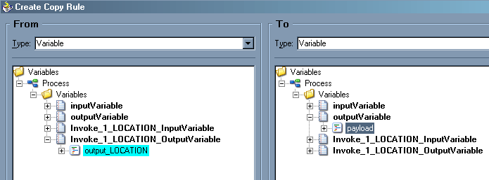
In the Create Copy Rule dialog box, map Invoke_1_LOCATION_OutputVariable > output_LOCATION to outputVariable > payload.
Verify that you have mapped all variables as follows:
Click OK, then click OK again.
Select Save from the File menu.
You have completed the design of your BPEL process.
Deploying the BPEL Process for the LOCATION Outbound Service
JDeveloper deploys the outbound BPEL process directly to Oracle BPEL Console.
To deploy your BPEL process in JDeveloper:
Right-click your process flow in the Applications - Navigator pane.
Select Deploy > Your BPEL PM Server connection > Deploy to default domain.
The Password Prompt dialog box is displayed.
Enter your BPEL Process Manager password in the Password Prompt dialog box.
The deployment process starts automatically after you enter the correct password.
Observe the Messages log on the bottom of the window.
The Messages log displays the deployment status. In this example, it shows a successful deployment message for the process.

If deployment was not successful, click the Compiler tab to view all error and warning messages generated during the deployment process.
To invoke the LOCATION process from Oracle BPEL Console:
Start the Oracle BPEL Console by entering the following URL in a browser:
http://host:port/BPELConsole
Select a domain and provide a valid password.
The Oracle BPEL Console main page is displayed.
The Initiate tab enables you to test your BPEL process.
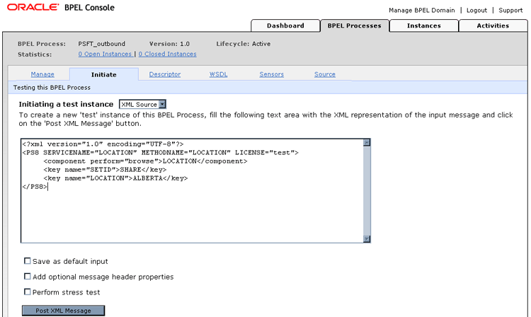
Perform the following steps:
From the Initiating a test instance drop-down menu, select XML Source.
Enter the following code in the text area provided for XML input:
<?xml version="1.0" encoding="UTF-8"?>
<PS8 SERVICENAME="LOCATION" METHODNAME="LOCATION" LICENSE="test">     <component perform="browse">LOCATION</component>     <key name="SETID">SHARE</key>     <key name="LOCATION">ALBERTA</key></PS8>
Click Post XML Message.
The response received from the PeopleSoft system is displayed in the Initiate window.