|
Oracle® BPEL Process Manager Developer's Guide
10g Release 2 (10.1.2) B14448-02 |
|
 Previous |
 Next |
|
Oracle® BPEL Process Manager Developer's Guide
10g Release 2 (10.1.2) B14448-02 |
|
 Previous |
 Next |
This chapter describes how to start key Oracle BPEL Process Manager components, including JDeveloper BPEL Designer, Eclipse BPEL Designer, Oracle BPEL Server, and Oracle BPEL Console. An overview of the main sections of JDeveloper BPEL Designer and Eclipse BPEL Designer that you use to design BPEL processes is also provided. Key BPEL design components such as activities and partner links and the services and adapters that Oracle BPEL Process Manager provides to add value and ease of use to standard BPEL functionality are also described.
This chapter contains the following topics:
The Oracle BPEL Process Manager consists of the three components shown in Figure 2-1.
Figure 2-1 Oracle BPEL Process Manager Components
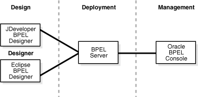
Each component enables you to perform a specific set of tasks:
The design environment (JDeveloper BPEL Designer or Eclipse BPEL Designer) enables you to design and deploy BPEL processes. You design BPEL processes by dragging and dropping elements (known as activities) into the process and editing their property pages. You integrate BPEL processes with external services that you also design and edit (known as partner links). You also use wizards to integrate technology adapters and services such as workflows, worklists, transformations, notifications, and sensors with the process.
When design is complete, you deploy the process from the design environment to Oracle BPEL Server.
If deployment is successful, you can run and manage the BPEL process from Oracle BPEL Console.
This chapter provides an overview of getting started with these components.
As described in Chapter 1, "Introduction to Oracle BPEL Process Manager", Oracle BPEL Process Manager provides support for two types of BPEL designer environments for graphically designing and deploying BPEL processes:
JDeveloper BPEL Designer
Eclipse BPEL Designer
Follow these instructions to start Oracle BPEL Process Manager components on JDeveloper BPEL Designer and Eclipse BPEL Designer.
Select Start, then All Programs, then Oracle - Oracle_Home, then Oracle BPEL Process Manager version_number, and then Start BPEL PM Server to start Oracle BPEL Server, which enables you to use the BPEL designer.
For JDeveloper BPEL Designer only, select Start, then All Programs, then Oracle - Oracle_Home, then Oracle BPEL Process Manager version_number, and then JDeveloper BPEL Designer. The designer enables you to design and deploy BPEL processes graphically.
For Eclipse BPEL Designer only, select Start, then All Programs, then Oracle - Oracle_Home, then Oracle BPEL Process Manager version_number, and then BPEL Designer. The designer enables you to design and deploy BPEL processes graphically.
Select Start, then All Programs, then Oracle - Oracle_Home, then Oracle BPEL Process Manager version_number, and then Developer Prompt to open up a command prompt at the Oracle_Home\integration\orabpel\samples directory. This enables you to access tutorials, demonstrations, and reference materials and start any required tutorial Web services.
Select Start, then All Programs, then Oracle - Oracle_Home, then Oracle BPEL Process Manager version_number, and then BPEL Console to start Oracle BPEL Console from which to run, monitor, and administer BPEL processes.
For JDeveloper BPEL Designer only, select Start, then All Programs, then Oracle - Oracle_Home, then Oracle BPEL Process Manager 10.1.2, and then Sample Worklist Application to start the sample Oracle BPEL Worklist Application.
For JDeveloper BPEL Designer only, select Start, then All Programs, then Oracle - Oracle_Home, then Oracle BPEL Process Manager 10.1.2, and then Getting Started with Samples for an overview of available tutorials, demonstrations, and reference materials in the Oracle_Home\integration\orabpel\samples directory.
|
Note: The version number that appears after Oracle BPEL Process Manager in the Start Menu sequence is determined by whether you are using JDeveloper BPEL Designer or Eclipse BPEL Designer. |
|
See Also:
|

This section provides an overview of the two types of BPEL designer environments for which Oracle BPEL Process Manager provides support:
This section provides an overview of JDeveloper BPEL Designer. In this overview, you first create a workspace and a project. A workspace is a container in which to place projects. A project contains the BPEL process.
Create a workspace by selecting File, then New, and then Application Workspace and providing the required details in the Create Application Workspace window (including selecting not to add a new empty project).
Right-click the newly created workspace and select New Project.
Double-click BPEL Process Project and provide the required details (including BPEL process name) in the BPEL Process Project window. A single project can contain only one BPEL process.
After you create the workspace and project, JDeveloper BPEL Designer displays the sections shown in Figure 2-2. You can also access this view by selecting View, and then Applications Navigator and double-clicking the .bpel file of the project. In this example, the project is an asynchronous type and is named OrderBooking.
Figure 2-2 JDeveloper BPEL Designer Sections
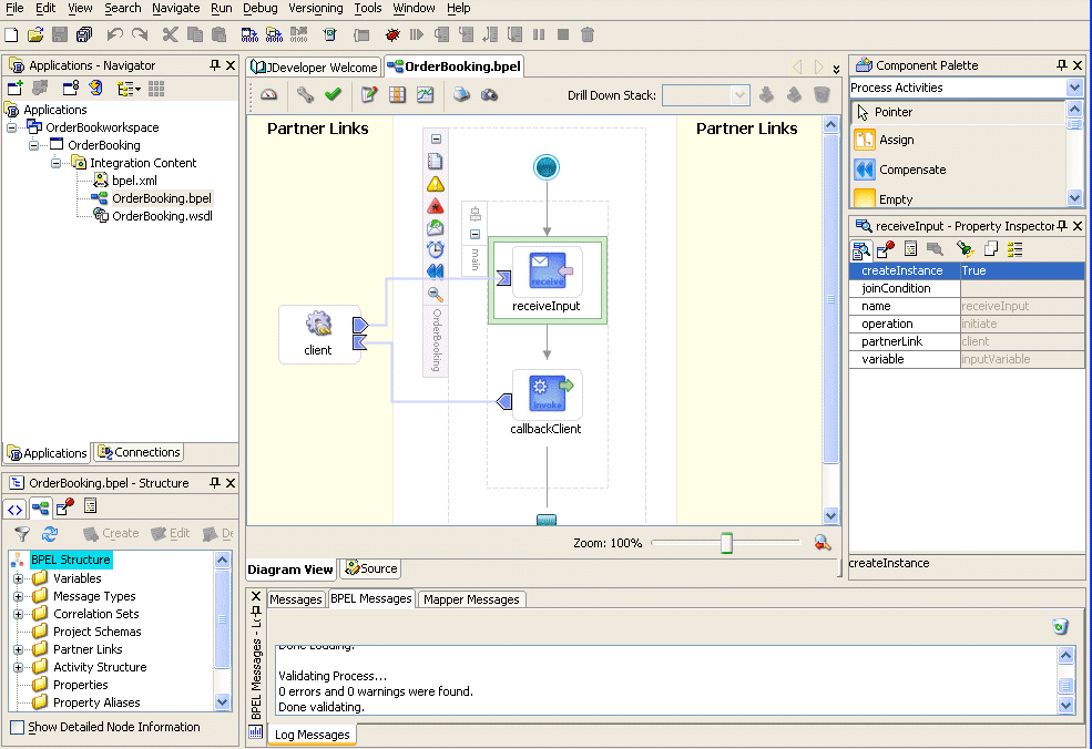
Each section of this view enables you to perform specific design and deployment tasks. Table 2-1 identifies the sections listed in Figure 2-2 and provides references to sections that describe their capabilities.
Table 2-1 JDeveloper BPEL Designer Sections
| Section | Location in Figure 2-2 | See Section |
|---|---|---|
|
Upper left |
|
|
|
Middle |
||
|
Upper right |
|
|
|
Lower right |
|
|
|
Lower left |
|
|
|
Bottom |
|
|
See Also: Oracle BPEL Process Manager Quick Start Guide and Oracle BPEL Process Manager Order Booking Tutorial for tutorials in which you create workspaces and projects |
The Application Navigator shown in the upper left part of Figure 2-2 displays the project files. Double-click a node (for example, the Integration Content node) to display its contents. Right-click a node to display a context-sensitive menu of commands. The menu commands that are available depend on the node selected. For example, if you right-click the FulfillOrder project in Figure 2-3, you can compile and deploy this BPEL process to Oracle BPEL Server.
Figure 2-3 shows the files that appear under the Integration Content folder when you first create a project in JDeveloper BPEL Designer (in this example, named FulfillOrder inside a workspace named OrderBookworkspace).
Table 2-2 describes these initial project files.
Table 2-2 Initial Project Files
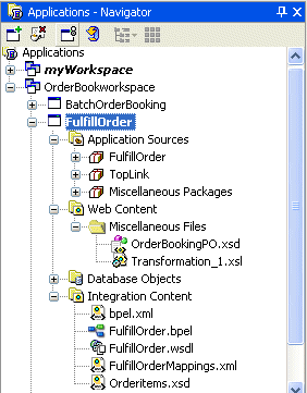
As you design the project, additional files, folders, and elements can appear in the Applications Navigator. For example, Figure 2-4 shows the files that appear for a project in which you imported a schema (OrderBookingPO.xsd), configured the database adapter (under the Application Sources node), and created a transform activity (Transformation_1.xsl under the Miscellaneous Files folder of the Web Content node). The Application Sources node contains Java source files. The Java classes are used inside callouts from the BPEL process. Additional folders can appear, such as BPEL-INF (a special directory for Java JAR files).
Figure 2-4 Applications Navigator (Expanded)
|
Note: If you want to learn more about the Application Navigator, place the cursor in this section and press F1 to display online Help. |
The Diagram View shown in the middle of Figure 2-2 provides a visual view of the BPEL process that you design. This view displays when you perform one of the following actions:
Double-click the .bpel file name in the Applications Navigator
Click the Diagram View tab at the bottom of the window with the .bpel file selected
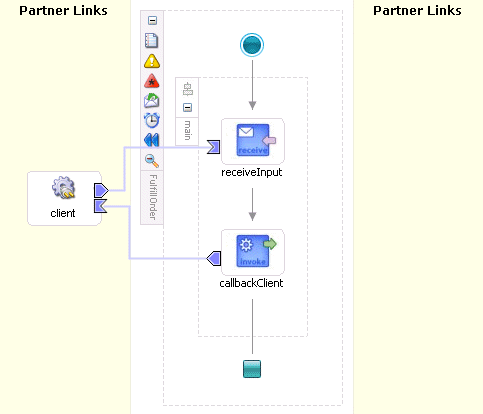
Figure 2-5 shows the activities automatically created with an asynchronous project. In the tutorials described in Oracle BPEL Process Manager Quick Start Guide and Oracle BPEL Process Manager Order Booking Tutorial, you add to the BPEL process by dragging and dropping activities, creating variables, creating partner links, and so on.
Figure 2-5 Diagram View (After Creation of an Asynchronous Project)
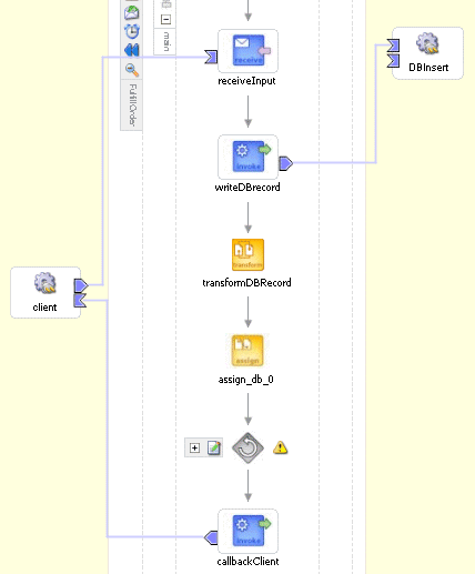
As you design the project by dragging and dropping activities, creating partner links, and so on, the Diagram View changes. Figure 2-6 shows the Diagram View later in the design phase after adding a partner link (in this example, named DBInsert) and the necessary activities (invoke, receive, assign, transform, and others).
Figure 2-6 Diagram View (After Design Phase)
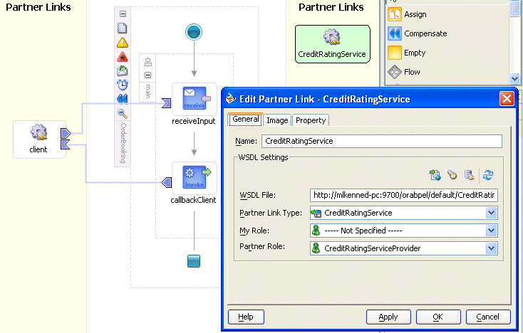
Click Source at the bottom to view the syntax inside the BPEL process project files. As you drag and drop activities and partner links, and perform other tasks, the syntax in these source files is immediately updated to reflect these changes. For example, Figure 2-7 shows the CreditRatingService partner link icon and property sheet that have just been created.
Figure 2-7 CreditRatingService Partner Link Icon and Property Sheet
Click Source at the bottom of the window. Figure 2-8 shows part of the Source of a .bpel file. Details about the CreditRatingService partner link you created appear in the file.
|
See Also: The following documentation for examples and descriptions of the types of syntax that appear in project files:
|
Activities are the building blocks of the BPEL process. The Process Activities selection of the Component Palette shown in the upper right part of Figure 2-2 displays a set of activities that you drag and drop into the Diagram View of the BPEL process. The Component Palette displays only those pages relevant to the state of the Diagram View. Process Activities is nearly always visible. However, if you are designing a transformation in a transform activity, the Component Palette only displays selections relevant to that activity, such as String Functions, Mathematical Functions, and Node-set Functions.
Figure 2-9 shows the Process Activities selection of the Component Palette.
Figure 2-9 Component Palette - Process Activities
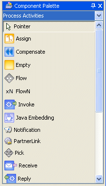
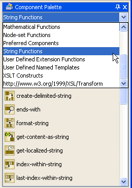
Figure 2-10 shows the String Functions category of the Component Palette that displays when you work in the transformation window of a transform activity.
Figure 2-10 Component Palette - Functions
|
Note: If you want to learn more about the Component Palette, place the cursor in this section and press F1 to display online Help. |
The Property Inspector shown in the lower right part of Figure 2-2 enables you to view details about an activity. Single-click an activity in the Diagram View. For example, single-clicking the receiveInput receive activity shown in Figure 2-2 displays the information shown in Figure 2-11.
The Structure Window shown in the lower left part of Figure 2-2 offers a structural view of the data in the project currently selected in the Diagram View. You can perform a variety of tasks from this section, including:
Importing project schemas
Defining message types
Managing (creating, editing, and deleting) elements such as variables, aliases, correlation sets, partner links, and sensors
Editing activities in the BPEL process flow sequence that displays in the Diagram View
Figure 2-12 shows the Structure Window. In this example, the window has been expanded to display the imported project schemas and the sequence of activities in the Diagram View for the FulfillOrder project shown in Figure 2-6.
You validate, compile, and deploy a process by right-clicking the project name in the Applications Navigator, selecting Deploy, and selecting a deployment method. The Log Window shown at the bottom of Figure 2-2 then displays messages about the status of the deployment.
To ensure that a process validates correctly, you must ensure that the following information is correct:
The process must have an input variable.
A partner link must be selected.
A partner role must be selected.
The operation must not be empty.
The input variable type must match the partner link operation type.
Figure 2-13 shows a successful deployment message for a BPEL process. You can then run, monitor, and administer the process from Oracle BPEL Console.
Figure 2-13 Successful Deployment Message

If deployment is unsuccessful, messages appear that describe the type and location of the error, as shown in Figure 2-14. Double-click the error to navigate directly to the offending line in the source file referenced.
Figure 2-14 Unsuccessful Deployment Message

|
Note: If you want to learn more about the Log Window, place the cursor in this section and press F1 to display online Help. |
|
See Also:
|
Note the following issues when editing the bpel.xml, WSDL, and BPEL files:
The bpel.xml file content is only read into memory when the file is opened. Therefore, if you change the content of bpel.xml after the file is opened, the changes are not made in memory. After changing the content of the BPEL file, close and reopen the file for the changes to take effect.
Do not edit the bpel.xml file through a combination of JDeveloper BPEL Designer and a text editor such as Notepad or Wordpad. Use only a single editing environment such as JDeveloper BPEL Designer.
Do not edit the bpel.xml file, BPEL files, and WSDL files while changing the design of the process. If you want to edit a file:
Ensure that the BPEL files are not being edited in JDeveloper BPEL Designer. If they are being edited (that is, a tab for that file is visible), close it and save changes as needed.
Edit the required file and save the changes.
This section provides an overview of Eclipse BPEL Designer. Eclipse BPEL Designer is similar to JDeveloper BPEL Designer. Differences between the two BPEL designers are described. In this overview, you first create a project for the BPEL process.
Select File, then New, and then Project to display the New Project window.
Select Oracle BPEL Project (the default selection) and click Next to display the Create a BPEL Project window.
Provide the required details (including BPEL process name) and click Finish. A single project can contain only one BPEL process.
After you create the project, Eclipse BPEL Designer displays the sections shown in Figure 2-15. You can also access this view by double-clicking the .bpel file of the project and selecting Process Map. In this example, the project is named myCreditFlow.
Figure 2-15 Eclipse BPEL Designer Sections
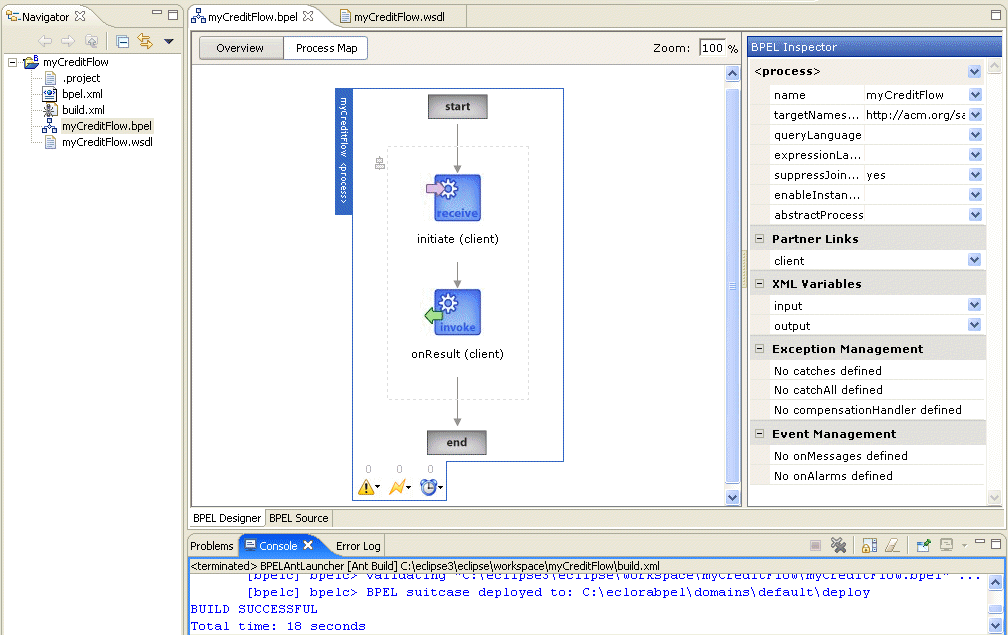
In addition, the BPEL Palette of activities displays on this page. If the BPEL Palette does not currently display, perform the following steps:
Select Show View, and then Other from the Windows main menu
Select BPEL, and then BPEL Palette on the Show View window, and click OK to display the BPEL Palette in Eclipse BPEL Designer.
Each section of this view enables you to perform specific design and deployment tasks. Table 2-3 identifies the sections listed in Figure 2-15 and Figure 2-16 and provides references to sections that describe their capabilities.
Table 2-3 Eclipse BPEL Designer Sections
| Section | Location | See Section |
|---|---|---|
|
Upper left of Figure 2-15 |
|
|
|
Middle of Figure 2-15 |
||
|
Right side of Figure 2-15 |
|
|
|
Bottom of Figure 2-15 |
|
|
|
|
|
|
See Also:
|
The Navigator shown in the upper left part of Figure 2-15 displays the project files in Eclipse BPEL Designer. See Table 2-2 for descriptions of the files that initially appear when you first create a project. Eclipse BPEL Designer also includes an additional project file: build.xml. This is an Apache Ant file used for compiling and deploying processes in Eclipse BPEL Designer.
The Process Map shown in the middle of Figure 2-15 provides a visual view of the BPEL process that you design. The Process Map is similar to the Diagram View window in JDeveloper BPEL Designer. This view displays when you perform one of the following actions:
Double-click the .bpel file name in the Navigator
Click the BPEL Designer tab; then click the Process Map tab
Figure 2-18 shows the activities automatically created with an asynchronous project. You add to the process by dragging and dropping activities, creating variables, creating partner links, and so on.
Click Overview to display an overview on the BPEL process, as shown in Figure 2-19. You can perform tasks such as adding partner links and creating variables in the Overview window.
|
See Also: The following tutorials that use Eclipse BPEL Designer to design BPEL processes:
|
The BPEL Source window is similar to that in JDeveloper BPEL Designer. Click Source Window to view the syntax inside the project files, which is similar to that shown for JDeveloper BPEL Designer in Figure 2-8.
The BPEL Inspector enables you to perform tasks such as editing existing activities, adding copy rules to an assign activity, creating global variables, creating partner links, and so on. Figure 2-20 shows the BPEL Inspector.
You validate, compile, and deploy a process by clicking the Build BPEL Project icon in the tool bar.

The Log Window at the bottom of Eclipse BPEL Designer then displays messages about the status of the deployment. Figure 2-21 shows a successful deployment message for a BPEL process. You can then run, monitor, and administer the process from Oracle BPEL Console.
|
See Also:
|
The BPEL Palette is similar to the Process Activities selection of the Component Palette in JDeveloper BPEL Designer. The BPEL Palette displays a set of activities that you drag and drop into the Process Map of the BPEL process. The set of activities available with Eclipse BPEL Designer differs slightly from those available with JDeveloper BPEL Designer. For example, unlike JDeveloper BPEL Designer, a partner link is not listed as a BPEL Palette activity in Eclipse BPEL Designer. JDeveloper BPEL Designer also includes additional activities for transformations, user tasks (workflows), and notifications.
The term activities has been mentioned frequently in both Chapter 1, "Introduction to Oracle BPEL Process Manager" and in this chapter. Activities are the building blocks of a BPEL process. JDeveloper BPEL Designer and Eclipse BPEL Designer both include a set of activities that you drag and drop into a BPEL process. You then double-click an activity to define its attributes (property values). Figure 2-6 provides an example of this design process. Activities enable you to perform specific tasks within a process. For example:
An assign activity enables you to manipulate data, such as copying the contents of one variable to another.

An invoke activity enables you to invoke a service (identified by its partner link) and specify an operation for this service to perform.

A receive activity waits for an asynchronous callback response message from a service.

Figure 2-23 shows an example of a property window (for this example, an invoke activity). In this example, you invoke a partner link named CreditRatingService and define its attributes.
|
See Also:
|
The term partner link has also been mentioned frequently in both Chapter 1, "Introduction to Oracle BPEL Process Manager" and in this chapter. A partner link enables you to define the external services with which the BPEL process is to interact. Figure 2-24 shows the partner link icon (in this example, named CreditRatingService).
A partner link type characterizes the conversational relationship between two services by defining the roles played by each service in the conversation and specifying the port type provided by each service to receive messages within the context of the conversation. Figure 2-6 shows an example of a partner link named DBInsert being invoked by a BPEL process.
Figure 2-25 shows an example of the attributes of a partner link for a service named RapidDistributors.
Table 2-4 describes the fields of the PartnerLink window.
Table 2-4 PartnerLink Window Fields
| Field | Description |
|---|---|
|
A unique and recognizable name you provide for the partner link. |
|
|
WSDL File |
The name and location of the Web Services Description Language (WSDL) file that you select for the partner link. Click the flashlight icon (second icon from the left above the WSDL File field) to access a window for selecting the WSDL file to use. |
|
Partner Link Type |
The partner link defined in the WSDL file. |
|
My Role |
The role performed by the BPEL process. In this case, the BPEL process is the requester. |
|
Partner Type |
The role performed by the partner link (in this example, the RapidDistributors service). In this case, RapidDistributors is the provider. |
After you complete the design of the BPEL process, you compile and deploy the process to Oracle BPEL Server. If compilation and deployment are successful, you can run and manage the BPEL process from Oracle BPEL Console.
Deployment sends the Oracle BPEL Process Manager archive (a set of files in a JAR file with a directory structure similar to the project directory structure) to Oracle BPEL Server. The deployment operation automatically validates and compiles the project directory into the BPEL archive.
Oracle BPEL Console enables you to run, monitor, and administer BPEL processes designed and deployed with either JDeveloper BPEL Designer or Eclipse BPEL Designer. You can also manage BPEL domains from Oracle BPEL Console. Access Oracle BPEL Console by selecting Start, then All Programs, then Oracle - Oracle_Home, then Oracle BPEL Process Manager version_number, and then BPEL Console.
Figure 2-26 shows the main page of Oracle BPEL Console. In this example, a number of deployed BPEL processes and external services appear in the Dashboard tab.
|
See Also:
|
Oracle BPEL Process Manager and JDeveloper BPEL Designer provide support for services that add value and ease of use to BPEL functionality.
Table 2-5 identifies and describes the services and provides references to sections of this guide that describe their capabilities.
Table 2-5 Oracle BPEL Process Manager Services
| Types | Description | See Section |
|---|---|---|
|
A transform activity is provided that enables you to create transformations that map source data to target data. For example, you can map incoming purchase order source data into outgoing purchase order acknowledgment target data. |
Chapter 14, "XSLT Mapper and Transformations" |
|
|
A notification activity enables you to send notification about an event to a user, group, or destination address. You can send a notification by e-mail, voice mail, fax, pager, or short message service (SMS). |
Chapter 15, "Oracle BPEL Process Manager Notification Service" |
|
|
Workflow enables you to integrate systems and services with human workflow into a single process flow. A user task activity is provided that invokes the Workflow wizard. This enables you to:
The criteria that you define with the Workflow wizard enables you to use the Oracle BPEL Worklist Application when you run the BPEL process. |
Chapter 16, "Oracle BPEL Process Manager Workflow Services" |
|
|
Oracle BPEL Worklist Application takes actions on tasks such as approving an employee vacation request, evaluating a job applicant, or escalating a purchasing decision. Based on the user profile, you access a URL that enables you to see all the tasks relevant to you and specify search criteria for displaying tasks. |
Chapter 17, "Worklist Application" |
|
|
You create sensors that you assign to activities, variables, and faults that you want to monitor during BPEL process run time. |
|
|
See Also: The following documentation for tutorials that describe how to design BPEL processes that use the services described in Table 2-5 |
The Partner Link Window shown in Figure 2-25 also enables you to take advantage of another key feature that Oracle BPEL Process Manager and JDeveloper BPEL Designer provide. Click the Define Adapter Service icon shown in Figure 2-27 to access the Adapter Configuration wizard.
Adapters enable you to integrate the BPEL processes with access to file systems, database tables, database queues, Java Message Services (JMS), and Oracle E-Business Suite. This wizard enables you to configure the types of adapters shown in Figure 2-28 for use with the BPEL process:
When you select an adapter type, the Service Name window shown in Figure 2-29 prompts you to enter a name. For this example, File Adapter was selected in Figure 2-28. When the wizard completes, a WSDL file by this service name appears in the Applications Navigator for the BPEL process (for this example, named ReadFile.wsdl). This file includes the adapter configuration settings you specify with this wizard. Other configuration files (such as header files and files specific to the adapter) are also created and display in the Applications Navigator.
The Adapter Configuration wizard windows that appear after the Service Name window are based on the adapter type you selected. These configuration windows and the information you must provide are described in later chapters of this guide.
|
See Also:
|
This chapter describes how to start key Oracle BPEL Process Manager components, including JDeveloper BPEL Designer, Eclipse BPEL Designer, Oracle BPEL Server, and Oracle BPEL Console. An overview of the main sections of JDeveloper BPEL Designer and Eclipse BPEL Designer that you use to design BPEL processes is also provided. Key BPEL design components such as activities and partner links and the services and adapters that Oracle BPEL Process Manager provides to add value and ease of use to standard BPEL functionality are also described.